background image


IVS-300 Embedded System 


Page 28 


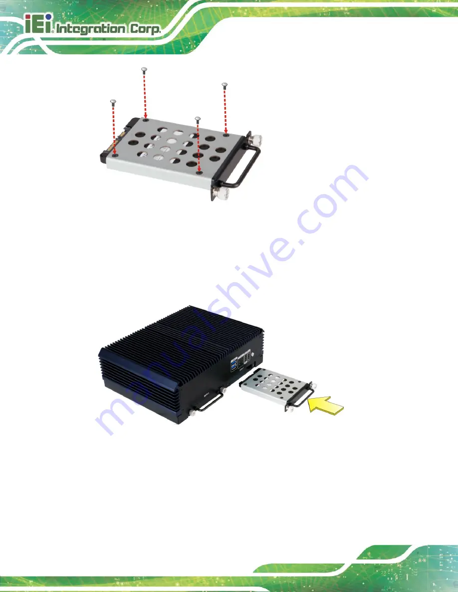
Figure 3-17: SSD Retention Screws 


Step 4: 

Carefully insert the SSD bracket into the slot on the front panel. Make sure the 

SATA connector on the SSD is securely connected to the SATA connector inside 

the chassis.   


Figure 3-18: SSD Installation 

Step 5: 

Tighten the two captive screws to secure the SSD bracket. 

Step 6: 

Repeat the five steps described above to install the second SSD into the other 

SSD bracket.   

Step 0:


Содержание IVS-300-ULT3-i5/4G

Страница 1: ...er Manual eIVS 300 Embedded System MODEL MODEL IVS 300 Fanless Embedded System with Intel Skylake ULT Baytrail Processor 4 GB DDR3L DDR4 Quad GbE LAN with PoE On board GPS HDMI VGA Dual SSD Bay RoHS C...

Страница 2: ...018 1 02 Eliminated mSATA support December 6 2017 1 01 Added some IVS 300 ULT3 specifications Added the optional OBD II cable and its connector pinouts Modified Section 3 13 Mobile AP Added Section 3...

Страница 3: ...heating do not operate it in an area that exceeds the maximum operating temperature described in the user manual Vorsicht Um eine berhitzung des Systems zu vermeiden betreiben Sie es ausschlie lich im...

Страница 4: ...o di un altro tipo di adattatore pu causare rischio d incendio o esplosione Si prega di fare riferimento al manuale utente per le specifiche sull alimentazione Atenci n Utilice solamente el adaptador...

Страница 5: ...arising out of the use or inability to use the product or documentation even if advised of the possibility of such damages This document contains proprietary information protected by copyright All ri...

Страница 6: ...ON Cautionary messages should be heeded to help reduce the chance of losing data or damaging the product NOTE These messages inform the reader of essential but non critical information These messages...

Страница 7: ...LIST 10 2 3 OPTIONAL ITEMS 11 3 INSTALLATION 13 3 1 ANTI STATIC PRECAUTIONS 14 3 2 INSTALLATION PRECAUTIONS 14 3 2 1 High Surface Temperature 15 3 3 INSTALLATION PROCEDURE 15 3 4 DISASSEMBLE THE SYSTE...

Страница 8: ...ILE AP 37 3 13 1 Installation 37 3 13 2 Usage 38 3 14 RAID CONFIGURATION ULT3 MODEL ONLY 39 4 BIOS 43 4 1 INTRODUCTION 44 4 1 1 Starting Setup 44 4 1 2 Using Setup 44 4 1 3 Getting Help 45 4 1 4 BIOS...

Страница 9: ...tem Doesn t Boot Up 74 5 2 3 More Troubleshooting 74 5 3 COMPONENT REPLACEMENT PROCEDURE 75 5 3 1 SO DIMM Replacement 75 A REGULATORY COMPLIANCE 77 B SAFETY PRECAUTIONS 82 B 1 SAFETY PRECAUTIONS 83 B...

Страница 10: ...ard into the Slot at an Angle 20 Figure 3 9 Securing the Full size PCIe Mini Card 20 Figure 3 10 Knockouts for External Antennas 22 Figure 3 11 WLAN and WWAN Card Slot Locations 22 Figure 3 12 Connect...

Страница 11: ...3 26 Power Input Connector 35 Figure 3 27 ACC Power Cable 35 Figure 3 28 Power Button 36 Figure 3 29 Mobile AP Connection 38 Figure 3 30 RAID Configuration BIOS Setting 40 Figure 5 1 SO DIMM Locations...

Страница 12: ...PCIE3 Pinouts 21 Table 3 2 WWAN Module Slot MINI PCIE1 Pinouts 24 Table 3 3 WLAN Module Slot MINI PCIE2 Pinouts 25 Table 3 4 RS 232 Connector Pinouts 30 Table 3 5 DIO and RS 422 485 Connector Pinouts...

Страница 13: ...u 49 BIOS Menu 6 Hardware Monitor 54 BIOS Menu 7 Smart Fan Mode Configuration 55 BIOS Menu 8 Power Management 57 BIOS Menu 9 CPU Configuration 59 BIOS Menu 10 IDE Configuration 61 BIOS Menu 11 USB Con...

Страница 14: ......

Страница 15: ...IVS 300 Embedded System Page 1 Chapter 1 1 Introduction...

Страница 16: ...rs with PoE ensure smooth network connectivity The display interface options include VGA and HDMI with two audio jacks Two USB 3 0 ports two RS 232 ports one RS 422 485 port and one OBD II port provid...

Страница 17: ...rt one OBD II port Two SATA 6Gb s SSD supported Two external SIM card slots support WWAN connection Optional 802 11b g n 1T1R wireless connection 1 4 Model Variations There are two models in the IVS 3...

Страница 18: ...hown in Figure 1 2 below Figure 1 2 Front Panel 1 5 1 LED Indicators The LED indicators on the front panel show the status of power HDD Wi Fi PoE and GPRS HSUPA connection Figure 1 3 LED Indicators Po...

Страница 19: ...led or the SIM slot is not being used Green The WWAN module is installed and the SIM slot is being used for WWAN connection Wi Fi LED Off The Wi Fi module is not installed Green The Wi Fi module is in...

Страница 20: ...The bottom surface of the IVS 300 contains six retention screw holes for installing two side mounting brackets Figure 1 5 Bottom Panel 1 8 Dimensions The dimensions of the IVS 300 are listed below an...

Страница 21: ...tem max 8 GB Preinstalled one 4 0 GB DDR3L SDRAM SO DIMM Ethernet 4 x PCIe GbE by Intel I210 Ethernet controller with PoE IEEE802 3af support GPS On board GPS Wireless LAN 1 x Half size PCIe Mini card...

Страница 22: ...nd one 4 GB DDR4 memory Operating Shock Half sine wave shock 5G 11ms 3 shocks per axis Operating Vibration MIL STD 810F 514 5C 2 with SSD Operating Temperature 20 C 60 C with air flow with SSD Storage...

Страница 23: ...IVS 300 Embedded System Page 9 Chapter 2 2 Unpacking...

Страница 24: ...Lift the system out of the boxes Step 5 Remove both polystyrene ends one from each side Step 6 Make sure all the components listed in the packing list are present 2 2 Packing List NOTE If any of the...

Страница 25: ...M3 5 for SSD installation 6 Screws M3 6 for mounting brackets 2 Mounting brackets 1 Driver and manual CD Table 2 1 Package List 2 3 Optional Items The following are optional component s which may be...

Страница 26: ...I KIT02 R10 WWAN kit P N IVS 3G KIT02 R10 OBD II cable P N 32025 003400 100 RS OS Image with Windows Embedded Standard 7 64 bit for IVS 300 BT DVD ROM RoHS P N IVS 300 BT WES7E64 R10 OS Image with Win...

Страница 27: ...IVS 300 Embedded System Page 13 Chapter 3 3 Installation...

Страница 28: ...rounding Before handling the board touch any grounded conducting material During the time the board is handled frequently touch any conducting materials that are connected to the ground Use an anti st...

Страница 29: ...ome surfaces of the equipment may become hot during operation The surface temperature may be up to several tens of degrees hotter than the ambient temperature Under these circumstances the equipment n...

Страница 30: ...rque for cover screws is 5 kg cm 0 36 lb ft 0 49 Nm 2 Never disassemble the system while power is still being fed into the system Before disassembling the system make sure the system has been turned o...

Страница 31: ...ention Screws Step 3 Remove the four internal retention screws Figure 3 2 Figure 3 2 Internal Chassis Retention Screws Step 4 Remove the front panel retention screws to detach the front panel from the...

Страница 32: ...rn the internal platform over to access the front side of the main board Figure 3 5 Internal Platform Removal 3 5 PCIe Mini Card Installation The PCIe Mini slot allows installation of either a full si...

Страница 33: ...ot Location Step 3 Remove the two retention screws as shown in Figure 3 7 Figure 3 7 Removing the Retention Screws Step 4 Line up the notch on the card with the notch on the slot Slide the PCIe Mini c...

Страница 34: ...he full size PCIe Mini card with the retention screws previously removed Figure 3 9 Figure 3 9 Securing the Full size PCIe Mini Card 3 5 1 PCIe Mini Slot MINI PCIE3 Pinouts The pinouts for the PCIe Mi...

Страница 35: ...35 GND 36 USB_DATA_N 37 NC 38 USB_DATA_P 39 VCC3 40 GND 41 VCC3 42 NC 43 DUAL3G LED 44 NC 45 NC 46 NC 47 NC 48 VCC1 5 49 NC 50 GND 51 NC 52 VCC3 Table 3 1 PCIe Mini Slot MINI PCIE3 Pinouts 3 6 WLAN WW...

Страница 36: ...tention screw s for PCIe Mini card installation Figure 3 11 Figure 3 11 WLAN and WWAN Card Slot Locations Step 5 Line up the notch on the WLAN WWAN module with the notch on the slot Slide the WLAN WWA...

Страница 37: ...onnector at the other end of the RF cable Step 9 Insert the SMA connector to the antenna connector hole on the rear panel Step 10 Secure the SMA connector by inserting the washer and tightening it wit...

Страница 38: ...ND 5 NC 6 VCC1 5 7 NC 8 SIM_VCC 9 GND 10 SIM_CIO 11 NC 12 SIM_CLK 13 NC 14 SIM_RST 15 GND 16 NC 17 NC 18 GND 19 NC 20 HSUPA_ON 21 GND 22 NC 23 NC 24 VCC3 25 NC 26 GND 27 GND 28 VCC1 5 29 GND 30 NC 31...

Страница 39: ...7 NC 8 NC 9 GND 10 NC 11 CLK_PCIE_CLK_N 12 NC 13 CLK_PCIE_CLK_P 14 NC 15 GND 16 NC 17 NC 18 GND 19 NC 20 NC 21 GND 22 PCIRST 23 PCIE_RXN 24 VCC3 25 PCIE_RXP 26 GND 27 GND 28 VCC1 5 29 GND 30 SMB_CLK...

Страница 40: ...IM 2 slot with the gold contacts facing up To remove the SIM card push the SIM card to release it Step 4 Install IEI Mobile AP to designate a SIM card to use The Mobile AP instruction is described in...

Страница 41: ...rews Step 2 Pull the bracket out to remove the bracket from the IVS 300 Figure 3 16 Figure 3 16 Removing SSD Bracket Step 3 Place an SSD onto the bracket and secure the SSD with the bracket by inserti...

Страница 42: ...on the front panel Make sure the SATA connector on the SSD is securely connected to the SATA connector inside the chassis Figure 3 18 SSD Installation Step 5 Tighten the two captive screws to secure t...

Страница 43: ...retention screw holes on the sides of the bottom surface Step 3 Secure the brackets to the system by inserting three retention screws M3 8 into each bracket Figure 3 19 Figure 3 19 Mounting Bracket R...

Страница 44: ...300 3 10 1 COM Port Connection The IVS 300 has two DB 9 connectors for RS 232 serial port connection The pinouts for the RS 232 connectors COM1and COM2 are listed in the figure and table below Figure...

Страница 45: ...he pinouts for the DIO and RS 422 485 connector are listed in the figure and table below Figure 3 21 DIO and RS 422 485 Connector PIN NO DESCRIPTION PIN NO DESCRIPTION 1 DIN0 9 DOUT3 2 DIN1 10 GND 3 D...

Страница 46: ...nouts for the OBD II J1939 connector are listed in the figure and table below Figure 3 22 OBD II J1939 Connector PIN NO DESCRIPTION 1 GND 2 GND 3 OBD CAN_H 4 ISO 9141 2 K 5 OBD CAN_L 6 J1850 7 J1850 8...

Страница 47: ...ser can purchase the optional OBD II cable Figure 3 23 to connect the IVS 300 with the vehicle OBD II Cable Figure 3 23 OBD II Cable The pinout locations of OBD II cable connector are shown below Figu...

Страница 48: ...eed Pulse Direction Connector Pinouts 3 11 Power On Procedure 3 11 1 Installation Checklist WARNING Make sure a power supply with the correct input voltage is being fed into the system Incorrect volta...

Страница 49: ...n power connector pinouts are listed in the figure and table below Figure 3 26 Power Input Connector PIN NO DESCRIPTION 1 GND 2 GND 3 GND 4 ACC 5 VIN 6 VIN Table 3 8 Power Input Connector Pinouts To u...

Страница 50: ...iver Installation NOTE The content of the CD may vary throughout the life cycle of the product and is subject to change without prior notice Visit the IEI website or contact technical support for the...

Страница 51: ...d to the system and install all of the necessary drivers for the IVS 300 3 13 Mobile AP IEI provides an application tool Mobile AP for the users of the IVS 300 with the WWAN module installed to manage...

Страница 52: ...ers and applications the IVS 300 must be restarted in order to complete the installation 3 13 2 Usage To launch the application double click the MobileAP icon on the Windows desktop The user interface...

Страница 53: ...value is internet o Connect result displays the connection result 3 14 RAID Configuration ULT3 Model Only The IVS 300 ULT3 i5 can provide data protection for serial ATA SATA disks via the Intel Rapid...

Страница 54: ...onfiguration If they are not the same size disk drive capacity is sacrificed and overall performance affected Step 2 Enable SATA drives in BIOS Start the computer and access the BIOS setup program Go...

Страница 55: ...igure the RAID array A Select the option to Create RAID Volume from the Main Menu and press Enter Intel R Rapid Storage Technology Option ROM 15 2 0 2748 Copyright C Intel Corporation All rights reser...

Страница 56: ...hen choose Y when the warning prompt appears to create volume Intel R Rapid Storage Technology Option ROM 15 2 0 2748 Copyright C Intel Corporation All rights reserved CREATE VOLUME MENU Name RAID Lev...

Страница 57: ...IVS 300 Embedded System Page 43 Chapter 4 4 BIOS...

Страница 58: ...1 Press the DELETE key as soon as the system is turned on or 2 Press the DELETE key when the Press Delete to enter SETUP message appears on the screen 0 If the message disappears before the DELETE ke...

Страница 59: ...Getting Help When F1 is pressed a small help window describing the appropriate keys to use and the possible selections for the highlighted item appears To exit the Help Window press ESC or the F1 key...

Страница 60: ...l SoC C0 Stepping Memory Information Total Memory 4096 MB LPDDR3 TXE Information Sec RC Version 00 05 00 00 TXE FW Version 01 00 02 1060 System Date Mon 08 17 2015 System Time 11 10 27 Access Level Ad...

Страница 61: ...tible with the hardware Aptio Setup Utility Copyright C 2016 American Megatrends Inc Main Advanced Chipset Security Boot Save Exit ACPI Settings Super IO Configuration Hardware Monitor Power Managemen...

Страница 62: ...highest ACPI sleep state the system will enter when the SUSPEND button is pressed Select Screen Select Item Enter Select Change Opt F1 General Help F2 Previous Values F3 Optimized Defaults F4 Save Ex...

Страница 63: ...s F3 Optimized Defaults F4 Save Exit ESC Exit Version 2 17 1245 Copyright C 2016 American Megatrends Inc BIOS Menu 4 Super IO Configuration 4 3 2 1 Serial Port n Configuration Use the Serial Port n Co...

Страница 64: ...o DEFAULT The serial port IO port address and interrupt address are automatically detected IO 3F8h IRQ 4 Serial Port I O port address is 3F8h and the interrupt address is IRQ4 IO 3F8h IRQ 3 4 5 6 7 9...

Страница 65: ...ort Change Settings Auto Use the Change Settings option to change the serial port IO port address and interrupt address Auto DEFAULT The serial port IO port address and interrupt address are automatic...

Страница 66: ...the Serial Port option to enable or disable the serial port Disabled Disable the serial port Enabled DEFAULT Enable the serial port Change Settings Auto Use the Change Settings option to change the se...

Страница 67: ...h and the interrupt address is IRQ3 4 5 6 7 9 10 11 12 IO 2E8h IRQ 3 4 5 6 7 9 10 11 12 Serial Port I O port address is 2E8h and the interrupt address is IRQ3 4 5 6 7 9 10 11 12 IO 3E0h IRQ 3 4 5 6 7...

Страница 68: ...3V 3 312 V VSB5V 4 944 V Enable or Disable Smart Fan Select Screen Select Item Enter Select Change Opt F1 General Help F2 Previous Values F3 Optimized Defaults F4 Save Exit ESC Exit Version 2 17 1245...

Страница 69: ...Fan Mode Configuration CPU_FAN1 Smart Fan Control Auto Duty Cycle Mode CPU Temperature 1 60 CPU Temperature 2 50 CPU Temperature 3 40 CPU Temperature 4 30 SYS_FAN1 Smart Fan Control Auto Duty Cycle Mo...

Страница 70: ...justs its speed using these settings CPU Temperature 1 CPU Temperature 2 CPU Temperature 3 CPU Temperature 4 SYS_FAN1 Smart Fan Control Auto Duty Cycle Mode Use the SYS_FAN1 Smart Fan Control BIOS opt...

Страница 71: ...Help F2 Previous Values F3 Optimized Defaults F4 Save Exit ESC Exit Version 2 17 1245 Copyright C 2016 American Megatrends Inc BIOS Menu 8 Power Management Low Voltage Warning 9V Use the Low Voltage...

Страница 72: ...wer State The following table shows the relation of the power state and vehicle ignition system The auto start up and shut down time delay can be set by the BIOS options listed above LOCK ACC ON START...

Страница 73: ...l Technology Select Screen Select Item Enter Select Change Opt F1 General Help F2 Previous Values F3 Optimized Defaults F4 Save Exit ESC Exit Version 2 17 1245 Copyright C 2016 American Megatrends Inc...

Страница 74: ...enable or disable virtualization on the system When combined with third party software Intel Virtualization technology allows several OSs to run on the same system at the same time Disabled DEFAULT Di...

Страница 75: ...tem Enter Select Change Opt F1 General Help F2 Previous Values F3 Optimized Defaults F4 Save Exit ESC Exit Version 2 17 1245 Copyright C 2016 American Megatrends Inc BIOS Menu 10 IDE Configuration Ser...

Страница 76: ...ect Change Opt F1 General Help F2 Previous Values F3 Optimized Defaults F4 Save Exit ESC Exit Version 2 17 1245 Copyright C 2016 American Megatrends Inc BIOS Menu 11 USB Configuration USB Devices The...

Страница 77: ...RNING Setting the wrong values for the Chipset BIOS selections in the Chipset BIOS menu may cause the system to malfunction Aptio Setup Utility Copyright C 2016 American Megatrends Inc Main Advanced C...

Страница 78: ...erican Megatrends Inc Chipset Intel IGD Configuration Memory Information Total Memory 4096 MB LPDDR3 DIMM1 2048 MB LPDDR3 DIMM2 2048 MB LPDDR3 Config Intel IGD Settings Select Screen Select Item Enter...

Страница 79: ...t Screen Select Item EnterSelect Change Opt F1 General Help F2 Previous Values F3 Optimized Defaults F4 Save Exit ESC Exit Version 2 17 1245 Copyright C 2016 American Megatrends Inc BIOS Menu 14 Intel...

Страница 80: ...ends Inc Chipset Audio Configuration Audio Controller Enabled XHCI Mode Smart Auto Control Detection of the Azalia device Disabled Azalia will be unconditionally disabled Enabled Azalia will be uncond...

Страница 81: ...et Security Boot Save Exit Password Description If ONLY the Administrator s password is set then this only limits access to Setup and is only asked for when entering Setup If ONLY the User s password...

Страница 82: ...Select Screen Select Item Enter Select Change Opt F1 General Help F2 Previous Values F3 Optimized Defaults F4 Save Exit ESC Exit Version 2 17 1245 Copyright C 2016 American Megatrends Inc BIOS Menu 17...

Страница 83: ...board lights up when the Number Lock is engaged Quiet Boot Enabled Use the Quiet Boot BIOS option to select the screen display when the system boots Disabled Normal POST messages displayed Enabled DEF...

Страница 84: ...evious Values F3 Optimized Defaults F4 Save Exit ESC Exit Version 2 17 1245 Copyright C 2016 American Megatrends Inc BIOS Menu 18 Save Exit Save Changes and Reset Use the Save Changes and Reset option...

Страница 85: ...IVS 300 Embedded System Page 71 Restore User Defaults Use the Restore User Defaults option to restore the user defaults to all the setup options...

Страница 86: ...IVS 300 Embedded System Page 72 Chapter 5 5 Troubleshooting and Maintenance...

Страница 87: ...ions may lead to personal injury and system damage To preserve the working integrity of the IVS 300 embedded system the system must be properly maintained If embedded system components need replacemen...

Страница 88: ...t up please do the following Step 1 Check the power is turned on See Section 5 2 1 above Step 2 Make sure the SO DIMM modules are properly installed Step 0 5 2 3 More Troubleshooting Nothing appears o...

Страница 89: ...resentative please send an email to sales ieiworld com The embedded system components listed below can all be replaced if they fail SO DIMM module PCIe Mini card see Section 3 5 WLAN or WWAN module se...

Страница 90: ...O DIMM must be aligned with the plastic bridge in the socket Figure 5 2 Step 5 Insert the SO DIMM Push the SO DIMM chip into the socket at an angle Figure 5 2 Figure 5 2 SO DIMM Installation Step 6 Op...

Страница 91: ...IVS 300 Embedded System Page 77 Appendix A A Regulatory Compliance...

Страница 92: ...nce with the essential requirements and other relevant provisions of Directive 2014 53 EU Bulgarian IEI Integration Corp 2014 53 EU esky Czech IEI Integration Corp t mto prohla uje e tento za zen je v...

Страница 93: ...EU Lietuvi Lithuanian IEI Integration Corp deklaruoja kad is ranga atitinka esminius reikalavimus ir kitas 2014 53 EU Direktyvos nuostatas Nederlands Dutch IEI Integration Corp dat het toestel toestel...

Страница 94: ...ili direktive 2014 53 EU Slovensky Slovak IEI Integration Corp t mto vyhlasuje e zariadenia sp a z kladn po iadavky a v etky pr slu n ustanovenia Smernice 2014 53 EU Suomi Finnish IE Integration Corp...

Страница 95: ...rference at his own expense Federal Communication Commission Interference Statement This equipment has been assembled with components that comply with the limits for a Class B digital device pursuant...

Страница 96: ...IVS 300 Embedded System Page 82 B Safety Precautions Appendix B...

Страница 97: ...the risk of electric shock make sure power cord is unplugged from wall socket To fully disengage the power to the unit please disconnect the power cord from the power outlet Refer servicing to qualif...

Страница 98: ...ptible to ESD It is therefore critical that whenever the IVS 300 is opened and any of the electrical components are handled the following anti static precautions are strictly adhered to Wear an anti s...

Страница 99: ...is classified as electronic device in terms of the European Directive 2012 19 EU WEEE and must not be disposed of as domestic garbage EU wide legislation as implemented in each Member State requires t...

Страница 100: ...n the embedded system gently wipe it with a piece of soft dry cloth or a slightly moistened cloth The interior of the device does not require cleaning Keep fluids away from the device interior Be caut...

Страница 101: ...the plastic parts Vacuum cleaner Using a vacuum specifically designed for computers is one of the best methods of cleaning the device Dust and dirt can restrict the airflow in the device and cause it...

Страница 102: ...IVS 300 Embedded System Page 88 Appendix C C BIOS Menu Options...

Страница 103: ...54 PC Health Status 54 CPU_FAN1 Smart Fan Control Auto Duty Cycle Mode 56 SYS_FAN1 Smart Fan Control Auto Duty Cycle Mode 56 Low Voltage Warning 9V 57 Auto Power On Delay 10 sec 57 Auto Power Off Dela...

Страница 104: ...IVS 300 Embedded System Page 90 Save Changes and Reset 70 Discard Changes and Reset 70 Restore Defaults 70 Save as User Defaults 70 Restore User Defaults 71...

Страница 105: ...IVS 300 Embedded System Page 91 Appendix D D Watchdog Timer...

Страница 106: ...IOS function call INT 15H is used to control the Watchdog Timer INT 15H AH 6FH Sub function AL 2 Sets the Watchdog Timer s period BL Time out value Its unit second is dependent on the item Watchdog Ti...

Страница 107: ...system resets Example program INITIAL TIMER PERIOD COUNTER W_LOOP MOV AX 6F02H setting the time out value MOV BL 30 time out value is 48 seconds INT 15H ADD THE APPLICATION PROGRAM HERE CMP EXIT_AP 1...

Страница 108: ...IVS 300 Embedded System Page 94 Appendix E E Hazardous Materials Disclosure...

Страница 109: ...mps These components will be separately marked Please refer to the following table Part Name Toxic or Hazardous Substances and Elements Lead Pb Mercury Hg Cadmium Cd Hexavalent Chromium CR VI Polybrom...

Страница 110: ...d System Page 96 RoHS RoHS Pb Hg Cd CR VI PBB PBDE O O O O O O O O O O O O O O O O O O O O O O O O O O O O O O O O O O O O O O O O O O O O O O O O O SJ T 11363 2006 GB T 26572 2011 X SJ T 11363 2006 G...

Отзывы: