


IOPS-Q67/H61 Pluggable Module PC
Page 47
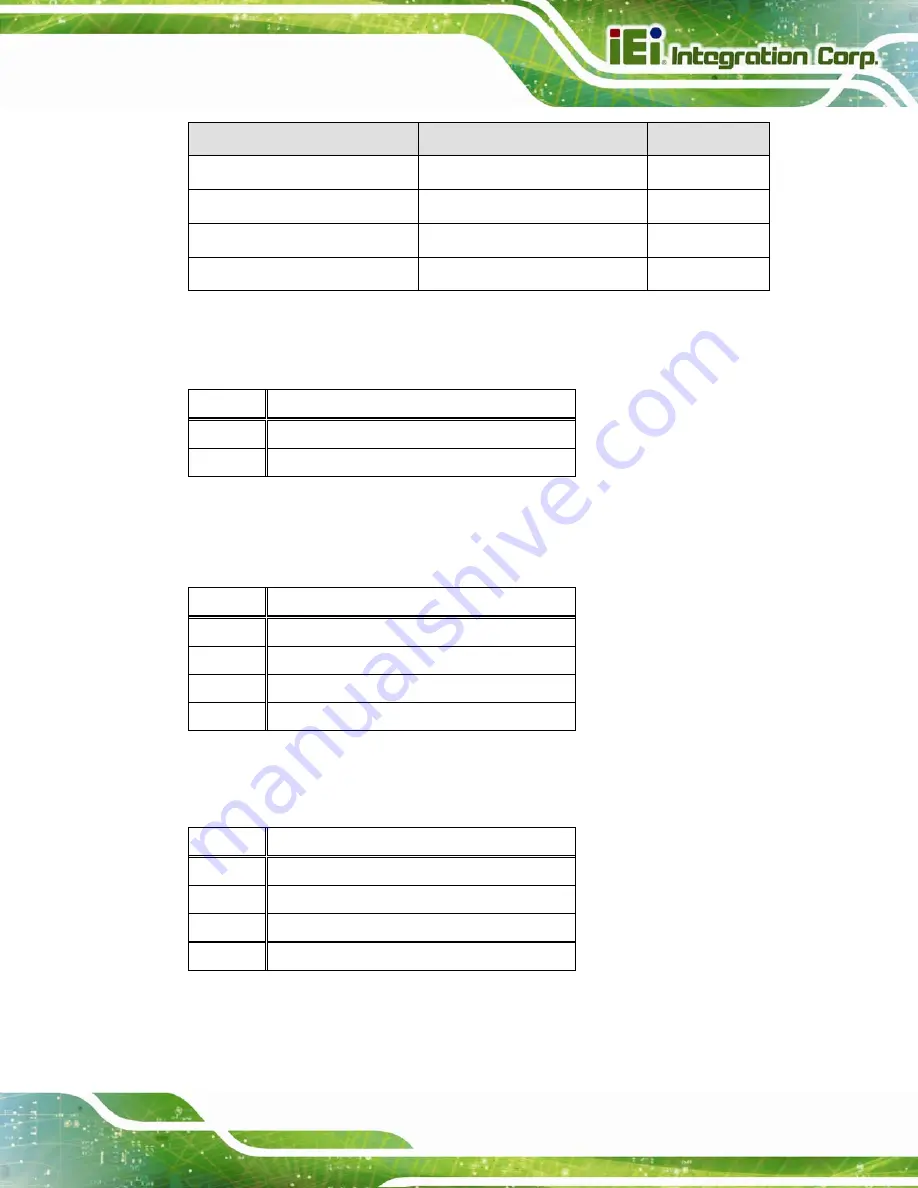
Connector
Type
Label
PCIe Mini card slots
Full-size PCIe Mini card slot
JP2
SD card slot
SD card slot
CN1
SO-DIMM connector
SO-DIMM connector
DIMM1
USB DOM connector
8-pin header
USB2
Table 6-1: Peripheral Interface Connectors
6.2.1 Battery Connector (BT1)
6.2.2 Fan Connector (FAN1)
6.2.3 GPIO87 to SIO Connector (SW2)
PIN NO.
DESCRIPTION
1 BATT
2 GND
Table 6-2: Battery Connector (BT1) Pinouts
PIN NO.
DESCRIPTION
1 GND
2 +12V
3 FB
4 PWM
Table 6-3: Fan Connector (FAN1) Pinouts
PIN NO.
DESCRIPTION
1 NC
2 GPIO
3 GND
4 NC
Table 6-4: GPIO87 to SIO Connector (SW2) Pinouts
Содержание IOPS-Q67/H61
Страница 11: ...IOPS Q67 H61 Pluggable Module PC Page 1 Chapter 1 1 Introduction...
Страница 19: ...IOPS Q67 H61 Pluggable Module PC Page 9 Chapter 2 2 Unpacking...
Страница 22: ...IOPS Q67 H61 Pluggable Module PC Page 12 Chapter 3 3 Installation...
Страница 32: ...IOPS Q67 H61 Pluggable Module PC Page 22 Chapter 4 4 BIOS Screens...
Страница 48: ...IOPS Q67 H61 Pluggable Module PC Page 38 Chapter 5 5 Maintenance...
Страница 54: ...IOPS Q67 H61 Pluggable Module PC Page 44 Chapter 6 6 Interface Connectors...
Страница 61: ...IOPS Q67 H61 Pluggable Module PC Page 51 Appendix A A Safety Precautions...
Страница 66: ...IOPS Q67 H61 Pluggable Module PC Page 56 Appendix B B BIOS Menu Options...
Страница 68: ...IOPS Q67 H61 Pluggable Module PC Page 58 Appendix C C Watchdog Timer...


