background image

2012/1/202012/1/20 


IMBA-G412IS A  ATX  Mo th e rb o a rd  

P a g e   145 

Ap p e n d ix 

E


Dig ita l I/O In te rfa c e  

Содержание IMBA-G412ISA-R20

Страница 1: ...X Motherboard Page i IEI Technology Corp Us er Manual MODEL IMBA G412ISA ATX Motherboard for Intel Core 2 Duo Quad CPU 800 1066 1333 MHz FSB DDR3 VGA LAN SATA 3Gb s PCIe x16 PCI ISA USB HD Audio RoHS...

Страница 2: ...6 2012164 IMBA G412ISA ATX Motherboard Page ii Revis ion Date Version Changes 6 March 2012 2 00 Update the version number 20 January 2012 1 01 Update the BIOS section 26 October 2010 1 00 Initial rele...

Страница 3: ...ntial damages arising out of the use or inability to use the product or documentation even if advised of the possibility of such damages This document contains proprietary information protected by cop...

Страница 4: ...2 4 OPTIONAL ITEMS 13 3 CONNECTORS 15 3 1 PERIPHERAL INTERFACE CONNECTORS 16 3 1 1 Layout 16 3 1 2 Peripheral Interface Connectors 17 3 1 3 External Interface Panel Connectors 18 3 2 INTERNAL PERIPHER...

Страница 5: ...ector 37 3 3 5 Serial Port Connector COM1 38 3 3 6 USB Connectors 39 3 3 7 VGA Connector 39 4 INSTALLATION 41 4 1 ANTI STATIC PRECAUTIONS 42 4 2 INSTALLATION CONSIDERATIONS 42 4 3 BASIC INSTALLATION 4...

Страница 6: ...tup 67 5 1 2 Using Setup 67 5 1 3 Getting Help 68 5 1 4 Unable to Reboot after Configuration Changes 68 5 1 5 BIOS Menu Bar 68 5 2 MAIN 69 5 3 ADVANCED 70 5 3 1 CPU Configuration 71 5 3 2 IDE Configur...

Страница 7: ...p Recovery Partition 123 C 2 5 Create Factory Default Image 125 C 3 SETUP PROCEDURE FOR LINUX 130 C 4 RECOVERY TOOL FUNCTIONS 133 C 4 1 Factory Restore 135 C 4 2 Backup System 136 C 4 3 Restore Your L...

Страница 8: ...tor Location 25 Figure 3 10 Memory Card Slot Location 26 Figure 3 11 PCIe Power Input Connector Location 26 Figure 3 12 Power Connector Location 27 Figure 3 13 Serial Port Connector Locations 28 Figur...

Страница 9: ...rive Connection 57 Figure 4 16 Dual RS 232 Cable Installation 58 Figure 4 17 Audio Connector 59 Figure 4 18 PS 2 Keyboard Mouse Connector 60 Figure 4 19 LAN Connection 61 Figure 4 20 Parallel Device C...

Страница 10: ...plete 129 Figure C 21 Press Any Key to Continue 130 Figure C 22 Partitions for Linux 131 Figure C 23 System Configuration for Linux 132 Figure C 24 Access menu lst in Linux Text Mode 132 Figure C 25 R...

Страница 11: ...3 9 Front Panel Connector Pinouts 23 Table 3 10 IDE Connector Pinouts 24 Table 3 11 Infrared Connector Pinouts 25 Table 3 12 PCIe Power Input Connector Pinouts 27 Table 3 13 Power Connector Pinouts 2...

Страница 12: ...3 Clear BIOS Jumper Settings 51 Table 4 4 COM 2 Function Select Jumper Settings 52 Table 4 5 CompactFlash Setup Jumper Settings 53 Table 4 6 LCD Voltage Selection Jumper Settings 54 Table 4 7 USB Powe...

Страница 13: ...are Health Configuration 84 BIOS Menu 8 Power Configuration 87 BIOS Menu 9 ACPI Configuration 88 BIOS Menu 10 Remote Access Configuration 89 BIOS Menu 11 USB Configuration 92 BIOS Menu 12 Trusted Comp...

Страница 14: ......

Страница 15: ...2012 1 202012 1 20 IMBA G412ISA ATX Motherboard Page 1 Chapter 1 1 Introduction...

Страница 16: ...A includes VGA output with up to QXGA resolution Multiple expansion cards may be added including PCIe x16 PCI and ISA interface Other features include four SATA 3Gb s dual PCIe GbE digital I O five RS...

Страница 17: ...compliant LGA775 CPU socket Supports two DDR3 DIMMs Supports dual display by VGA port and an optional PCIe x16 SDVO expansion card Two Gigabit Ethernet connectors Four SATA connectors Eight USB ports...

Страница 18: ...41 20 2012164 Page 4 IMBA G412ISA ATX Motherboard 1 4 Connectors The connectors on the IMBA G412ISA are shown in the figure below Figure 1 2 Connectors...

Страница 19: ...2012 1 202012 1 20 IMBA G412ISA ATX Motherboard Page 5 1 5 Dimens ions The main dimensions of the IMBA G412ISA are shown in the diagram below Figure 1 3 Dimensions mm...

Страница 20: ...0 2012164 Page 6 IMBA G412ISA ATX Motherboard 1 6 Data Flow Figure 1 4 shows the data flow between the system chipset the CPU and other components installed on the motherboard Figure 1 4 Data Flow Dia...

Страница 21: ...nel DDR3 SDRAM DIMMs system max 4 GB Graphic Engine Intel GMA X4500 Integrated Graphics VGA integrated in Intel G41 supports up to 2048 x 1536 75 MHz Southbridge Chips et Intel ICH7 BIOS UEFI BIOS Dig...

Страница 22: ...onnector via 5 pin header Parallel Port One external parallel port Serial ATA Four independent SATA channels with 3 0 Gb s data transfer rates IDE One 40 pin IDE connector CompactFlas h One CF Type II...

Страница 23: ...2012 1 202012 1 20 IMBA G412ISA ATX Motherboard Page 9 Phys ical Specifications Dimens ions 305 mm x 244 mm Weight Gros s Net 1200 g 750 g Table 1 1 Technical Specifications...

Страница 24: ...101 20 2012164 Page 10 IMBA G412ISA ATX Motherboard Chapter 2 2 Packing Lis t...

Страница 25: ...lectrostatic discharge Self grounding Touch a grounded conductor every few minutes to discharge any excess static buildup Use an anti static pad When configuring any circuit board place it on an anti...

Страница 26: ...or vendor the IMBA G412ISA was purchased from or contact an IEI sales representative directly by sending an email to sales iei com tw The IMBA G412ISA is shipped with the following components Quantity...

Страница 27: ...mber Image 1 Utility CD 1 Quick Installation Guide Table 2 1 Packing List 2 4 Optional Items The following are optional components which may be separately purchased Item and Part Number Image CPU cool...

Страница 28: ...Number Image ATA 66 100 flat cable P N 32200 000052 RS USB cable P N CB USB02 RS SATA power cable P N 32102 000100 200 RS DVI output SDVO card P N SDVO 100DVI R10 VGA output SDVO card P N SDVO 100VGA...

Страница 29: ...2012 1 202012 1 20 IMBA G412ISA ATX Motherboard Page 15 Chapter 3 3 Connectors...

Страница 30: ...16 IMBA G412ISA ATX Motherboard 3 1 Peripheral Interface Connectors This chapter details all the jumpers and connectors 3 1 1 Layout The figure below shows all the connectors and jumpers Figure 3 1 Co...

Страница 31: ...ctor 10 pin header DIO1 Front panel connector 14 pin header F_PANEL1 IDE connector 40 pin box header IDE1 Infrared connector 5 pin header IR1 ISA slots ISA slot ISA1 ISA2 Memory slot 240 pin DDR3 DIMM...

Страница 32: ...io jack AUDIO1 Keyboard Mouse connector PS 2 KBMS2 LAN connector RJ 45 LAN1 LAN2 Parallel port DB 25 Female 3IN1_DSUB1A Serial port connector DB 9 Male 3IN1_DSUB1B USB connector USB port USB1 USB2 VGA...

Страница 33: ...ion Pin Description 1 MIC_L 2 Audio GND 3 MIC_R 4 FP_AUO_DETECT 5 LINE_R 6 PD 7 F_SENSE 8 NC 9 LINE_L 10 PD Table 3 3 Audio Connector Pinouts 3 2 2 CPU Fan Connector CN Label CPU_FAN1 CN Type 4 pin wa...

Страница 34: ...2 12 V 3 Fan In 4 Fan Control Table 3 4 CPU Fan Connector Pinouts 3 2 3 Sys tem Fan Connectors CN Label NB_FAN1 SYS_FAN1 and SYS_FAN2 CN Type 3 pin wafer CN Location See Figure 3 4 CN Pinouts See Tabl...

Страница 35: ...Table 3 6 System Fan Connector Pinouts SYS_FAN2 and SYS_FAN3 3 2 4 CPU Power Input Connector CN Label CPU12V1 CN Type 4 pin connector CN Location See Figure 3 5 CN Pinouts See Table 3 7 The CPU power...

Страница 36: ...provides programmable input and output for external devices The digital I O provides 4 bit output and 4 bit input Figure 3 6 Digital I O Connector Location Pin Description Pin Description 1 GND 2 VCC5...

Страница 37: ...Figure 3 7 Front Panel Connector Location FUNCTION PIN DESCRIPTION FUNCTION PIN DESCRIPTION Power LED 1 Power LED Buzzer 2 BEEP_PWR 3 NC 4 NC 5 GND 6 NC Power Button 7 PWRBTSW 8 PC_BEEP 9 GND 10 NC HD...

Страница 38: ...ATA 7 4 DATA 8 5 DATA 6 6 DATA 9 7 DATA 5 8 DATA 10 9 DATA 4 10 DATA 11 11 DATA 3 12 DATA 12 13 DATA 2 14 DATA 13 15 DATA 1 16 DATA 14 17 DATA 0 18 DATA 15 19 GROUND 20 N C 21 IDE DRQ 22 GROUND 23 IOW...

Страница 39: ...on See Figure 3 9 CN Pinouts See Table 3 11 The infrared connector attaches to an infrared receiver for use with remote controls Figure 3 9 Infrared Connector Location Pin Description 1 5V 2 NC 3 IR R...

Страница 40: ...y modules Figure 3 10 Memory Card Slot Location 3 2 10 PCIe Power Input Connector CN Label PNC1 CN Type 3 pin wafer 1x3 CN Location See Figure 3 11 CN Pinouts See Table 3 12 The PCIe power input conne...

Страница 41: ...outs 3 2 11 Power Connector CN Label PWR2 CN Type 24 pin connector CN Location See Figure 3 12 CN Pinouts See Table 3 13 The power connector connects to an ATX power supply Figure 3 12 Power Connector...

Страница 42: ...3V 24 GND Table 3 13 Power Connector Pinouts 3 2 12 RS 232 Serial Port Connectors CN Label COM3 COM4 COM5 COM6 CN Type 10 pin box header CN Location See Figure 3 13 CN Pinouts See Table 3 14 This con...

Страница 43: ...2 13 RS 232 422 485 Serial Port Connector CN Label COM2 CN Type 14 pin box header CN Location See Figure 3 14 CN Pinouts See Table 3 15 This connector provides RS 232 RS 422 or RS 485 communications F...

Страница 44: ...SATA1 SATA2 SATA3 SATA4 CN Type 7 pin SATA drive connectors CN Location See Figure 3 15 The SATA drive connectors can be connected to SATA 3Gb s drives Figure 3 15 SATA Drive Connector Location 3 2 1...

Страница 45: ...onnector Locations Pin Description 1 GND 2 SMBDATA 3 SMBCLK 4 5V Table 3 16 SMBus Connector Pinouts 3 2 16 SPI Flas h Connector CN Label J SPI1 CN Type 8 pin header CN Location See Figure 3 17 CN Pino...

Страница 46: ...scription Pin Description 1 3 3V 2 GND 3 CS 4 CLOCK 5 SO 6 SI 7 NC 8 NC Table 3 17 SPI Flash Connector 3 2 17 TPM Connector CN Label TPM1 CN Type 20 pin header 2x10 CN Location See Figure 3 18 CN Pino...

Страница 47: ...T4 6 5 V 7 LAD3 8 LAD2 9 LAD0 10 LAD1 11 GND 12 GND 13 SMBCLK_MAIN 14 SMBDATA_MAIN 15 3 3 V 16 SERIRQ 17 GND 18 CLKRUN 19 3 3 V 20 LDRQ Table 3 18 TPM Connector Pinouts 3 2 18 USB Connectors CN Label...

Страница 48: ...on 1 5V 2 GND 3 USBP4 6 4 USBP5 7 5 USBP4 6 6 USBP5 7 7 GND 8 5V Table 3 19 USB Port Connector Pinouts 3 3 External Peripheral Interface Connector Panel The figure below shows the external peripheral...

Страница 49: ...D ROM DVD player or other audio devices Line Out port Lime Connects to a headphone or a speaker With multi channel configurations this port can also connect to front speakers Microphone Pink Connects...

Страница 50: ...NC 2 NC 9 GND 3 GND 10 5 V 4 5 V 11 MS_CLK 5 KB_CLK 12 NC 6 NC 13 KB_GND 7 MS_DATA 14 KB_GND Table 3 20 Keyboard Connector Pinouts 3 3 3 LAN Connectors CN Label LAN1 LAN2 CN Type RJ 45 CN Location See...

Страница 51: ...l 3IN1_DSUB1A CN Type DB 25 Female CN Location See Figure 3 20 CN Pinouts See Table 3 22 The parallel port connects to parallel port device typically a printer Pin Description Pin Description 1 STROBE...

Страница 52: ...1 CN Label 3IN1_DSUB1B COM1 CN Type DB 9 Male CN Location See Figure 3 20 CN Pinouts See Table 3 23 and Figure 3 24 The serial port connects to a RS 232 serial communications device Pin Description Pi...

Страница 53: ...connected to a USB device Pin Description Pin Description 1 USBPWR1 2 USBP0 2 3 USBP0 2 4 GND 5 USBPWR1 6 USBP1 3 7 USBP1 3 8 GND Table 3 24 USB Port Pinouts 3 3 7 VGA Connector CN Label 3IN1_DSUB1C...

Страница 54: ...ge 40 IMBA G412ISA ATX Motherboard Pin Description Pin Description 1 RED 2 GREEN 3 BLUE 4 CRT_PLUG 5 GND 6 GND 7 GND 8 GND 9 VGAVCC 10 GND 11 NC 12 DDC DAT 13 HSYNC 14 VSYNC 15 DDCCLK Table 3 25 VGA C...

Страница 55: ...2012 1 202012 1 20 IMBA G412ISA ATX Motherboard Page 41 Chapter 4 4 Ins tallation...

Страница 56: ...tatic wristband can help to prevent ESD from damaging the board Self grounding Before handling the board touch any grounded conducting material During the time the board is handled frequently touch an...

Страница 57: ...ESD from the body and helps prevent ESD damage Place the IMBA G412ISA on an antistatic pad o When installing or configuring the motherboard place it on an antistatic pad This helps to prevent potenti...

Страница 58: ...To enable Hyper Threading the CPU and chipset must both support it WARNING CPUs are expensive and sensitive components When installing the CPU please be careful not to damage it in anyway Make sure th...

Страница 59: ...e the protective cover The black protective cover can be removed by pulling up on the tab labeled Remove See Figure 4 2 Figure 4 2 Remove Protective Cover Step 2 Open the socket Disengage the load lev...

Страница 60: ...ate pin 1 and the two orientation notches on the CPU Carefully match the two orientation notches on the CPU with the socket alignment keys Step 7 Insert the CPU Gently insert the CPU into the socket I...

Страница 61: ...entally or otherwise the pre sprayed layer of thermal paste on the bottom of the heat sink The thermal paste between the CPU and the heat sink is important for optimum heat dissipation To install the...

Страница 62: ...de of the PCB align the support bracket to the screw threads on heat sink that were inserted through the PCB holes See Figure 4 6 Figure 4 6 Securing the Heat sink to the IMBA G412ISA Step 5 Tighten t...

Страница 63: ...t Align the DIMM so the notch on the memory lines up with the notch on the memory socket See Figure 4 7 Step 3 Insert the DIMM Once aligned press down until the DIMM is properly seated Clip the two ha...

Страница 64: ...clip and to OPEN a jumper means removing the plastic clip from a jumper The IMBA G412ISA includes some jumpers shown in Table 4 1 Des cription Label Type AT ATX power select jumpers JAUTO1 JAUTO2 2 pi...

Страница 65: ...ATX Power Select Jumper Settings Figure 4 8 AT ATX Power Select Jumper Location 4 4 2 Clear CMOS J umper J umper Label J P1 J umper Type 3 pin header J umper Settings See Table 4 3 J umper Location S...

Страница 66: ...er Location See Figure 4 10 The COM 2 Function Select jumper sets the communication protocol used by the second serial communications port COM 2 as RS 232 RS 422 or RS 485 The COM 2 Function Select se...

Страница 67: ...connection This jumper sets the CompactFlash card as the master or slave IDE device Setting Description Short Master Default Open Slave Table 4 5 CompactFlash Setup Jumper Settings Figure 4 11 Compact...

Страница 68: ...Figure 4 12 LCD Voltage Selection Jumper Location 4 4 6 USB Power Select J umpers J umper Label USBPW12 USBP34 J umper Type 3 pin header J umper Settings See Table 4 7 J umper Location See Figure 4 13...

Страница 69: ...Connection The IMBA G412ISA is shipped with two SATA drive cables and one SATA drive power cable To connect the SATA drives to the connectors please follow the steps below Step 1 Locate the connectors...

Страница 70: ...onnection Step 3 Connect the cable to the SATA disk Connect the connector on the other end of the cable to the connector at the back of the SATA drive See Figure 4 15 Step 4 Connect the SATA power cab...

Страница 71: ...cable is then attached to a D sub 9 male connector that is mounted onto a slot To install the dual RS 232 cable please follow the steps below Step 1 Locate the connectors The locations of the RS 232 c...

Страница 72: ...ernal Peripheral Interface Connection This section describes connecting devices to the external connectors on the IMBA G412ISA 4 6 1 Audio Connector The audio jacks on the external audio connector ena...

Страница 73: ...hone Pink Connects to a microphone Figure 4 17 Audio Connector Step 3 Check audio clarity Check that the sound is coming through the right speakers by adjusting the balance front to rear and left to r...

Страница 74: ...Mouse Connector 4 6 3 LAN Connection There are two external RJ 45 LAN connectors The RJ 45 connectors enable connection to an external network To connect a LAN cable with an RJ 45 connector please fo...

Страница 75: ...nnection The IMBA G412ISA has a single female DB 25 connector on the external peripheral interface panel for parallel devices Follow the steps below to connect a parallel device to the IMBA G412ISA St...

Страница 76: ...erial Device Connection The IMBA G412ISA has one male DB 9 connectors on the external peripheral interface panel for a serial device Follow the steps below to connect a serial device to the IMBA G412I...

Страница 77: ...Connection The external USB Series A receptacle connectors provide easier and quicker access to external USB devices Follow the steps below to connect USB devices to the IMBA G412ISA Step 1 Locate th...

Страница 78: ...412ISA please follow the instructions below Step 1 Locate the female DB 15 connector The location of the female DB 15 connector is shown in Chapter 3 Step 2 Align the VGA connector Align the male DB 1...

Страница 79: ...on All the drivers for the IMBA G412ISA are on the CD that came with the system To install the drivers please follow the steps below Step 1 Insert the CD into a CD drive connected to the system NOTE I...

Страница 80: ...661 20 2012164 Page 66 IMBA G412ISA ATX Motherboard Chapter 5 5 BIOS...

Страница 81: ...DELETE key is pressed restart the computer and try again 5 1 2 Us ing Setup Use the arrow keys to highlight items press ENTER to select use the PageUp and PageDown keys to change entries press F1 for...

Страница 82: ...ges If the computer cannot boot after changes to the system configuration is made CMOS defaults Use the jumper described in Chapter 4 5 1 5 BIOS Menu Bar The menu bar on top of the BIOS screen has the...

Страница 83: ...e Select Screen Select Item Change Field Tab Select Field F1 General Help F10 Save and Exit ESC Exit v02 61 Copyright 1985 2006 American Megatrends Inc BIOS Menu 1 Main Sys tem Overview The System Ove...

Страница 84: ...OS SETUP UTILITY Main Advanced PCIPnP Boot Security Chipset Exit Advanced Settings WARNING Setting wrong values in below sections may cause system to malfunction CPU Configuration IDE Configuration Su...

Страница 85: ...l Help F10 Save and Exit ESC Exit v02 61 Copyright 1985 2006 American Megatrends Inc BIOS Menu 3 CPU Configuration The CPU Configuration menu BIOS Menu 3 lists the following CPU details Manufacturer L...

Страница 86: ...Menu 4 IDE Configuration ATA IDE Configuration Enhanced Use the ATA IDE Configuration option to configure the ATA IDE controller Disabled Disables the on board ATA IDE controller Compatible Configure...

Страница 87: ...llowing IDE devices are detected and are shown in the IDE Configuration menu Primary IDE Master Primary IDE Slave Secondary IDE Master Secondary IDE Slave Third IDE Master Third IDE Slave The IDE Conf...

Страница 88: ...isted as follows Device Lists the device type e g hard disk CD ROM etc Type Indicates the type of devices a user can manually select Vendor Lists the device manufacturer Size List the storage capacity...

Страница 89: ...specified channel CD DVD The CD DVD option specifies that an IDE CD ROM drive is attached to the specified IDE channel The BIOS does not attempt to search for other types of IDE disk drives on the sp...

Страница 90: ...ve and the programmable IDE controller As the PIO mode increases the cycle time decreases Auto DEFAULT BIOS auto detects the PIO mode Use this value if the IDE disk drive support cannot be determined...

Страница 91: ...a maximum data transfer rate of 16 6MBps UDMA1 Ultra DMA mode 0 selected with a maximum data transfer rate of 16 6MBps UDMA1 Ultra DMA mode 1 selected with a maximum data transfer rate of 25MBps UDMA2...

Страница 92: ...M A R T BIOS option enables or disables this function Auto DEFAULT BIOS auto detects HDD SMART support Disabled Prevents BIOS from using the HDD SMART feature Enabled Allows BIOS to use the HDD SMART...

Страница 93: ...ess 328 Serial Port6 IRQ IRQ10 IR Function COM6 Parallel Port Address 378 Parallel Port Mode Normal Parallel Port IRQ IRQ7 Allows BIOS to select Serial Port1 Base Addresses Select Screen Select Item C...

Страница 94: ...port 2 IRQ address is IRQ4 IRQ3 DEFAULT Serial port 2 IRQ address is IRQ3 Select RS232 or RS422 RS485 RS232 Use the Select RS232 or RS422 RS485 option to select the Serial Port 2 signaling mode RS232...

Страница 95: ...port 4 10 DEFAULT Serial port 4 IRQ address is 10 Serial Port5 Addres s 338 Use the Serial Port5 Address option to select the Serial Port 5 base address Disabled No base address is assigned to Serial...

Страница 96: ...s 378 Use the Parallel Port Address option to select the parallel port base address Disabled No base address is assigned to the Parallel Port 378 DEFAULT Parallel Port I O port address is 378 278 Par...

Страница 97: ...ECP EPP The parallel port operates in the extended capabilities port ECP mode The ECP mode supports bi directional communication between the system and the parallel port device and the transmission ra...

Страница 98: ...of Lowest 020 NB FAN Highest Setting 100 NB FAN Second Setting 080 NB FAN Third Setting 070 NB FAN Fourth Setting 060 NB FAN Lowest Setting 050 CPU Temperature 16 C 60 F System Temperature 28 C 82 F C...

Страница 99: ...127 CPU Fan Highes t Setting 100 F81865 only support full speed in highest speed value CPU Fan Second Third Fourth Lowes t Setting n Use the or key to change the CPU Fan Second Third Fourth Lowest sp...

Страница 100: ...rth Lowest speed Enter a decimal number between 12 and 100 Monitored Values The following system parameters and values are shown The system parameters that are monitored are The following system tempe...

Страница 101: ...nd Exit ESC Exit v02 61 Copyright 1985 2006 American Megatrends Inc BIOS Menu 8 Power Configuration Select AT ATX Power BY HARDWARE Sets the behavior of the power AT Power ATX Power BY HARDWARE DEFAUL...

Страница 102: ...on to specify the sleep state the system enters when it is not being used S1 POS DEFAULT System appears off The CPU is stopped RAM is refreshed the system is running in a low power mode S3 STR System...

Страница 103: ...1985 2006 American Megatrends Inc BIOS Menu 10 Remote Access Configuration Remote Acces s Dis abled Use the Remote Access option to enable or disable access to the remote functionalities of the syste...

Страница 104: ...m is remotely accessed through COM5 COM6 System is remotely accessed through COM6 NOTE Make sure the selected COM port is enabled through the Super I O configuration menu Bas e Addres s IRQ 3F8h 4 The...

Страница 105: ...redirected after POST Boot Loader Redirection is active during POST and during Boot Loader Always DEFAULT Redirection is always active Some OSes may not work if set to Always Terminal Type ANSI Use t...

Страница 106: ...n to enable or disable the USB controllers Disabled USB controllers are enabled Enabled DEFAULT USB controllers are disabled USB 2 0 Controller Enabled The USB 2 0 Controller BIOS option enables or di...

Страница 107: ...is capable of operating at high speed 480 Mb s 5 3 8 Trus ted Computing Use the Trusted Computing menu BIOS Menu 12 to configure settings related to the Trusted Computing Group TCG Trusted Platform M...

Страница 108: ...may cause system to malfunction IRQ3 Reserved IRQ4 Reserved IRQ5 Available IRQ7 Available IRQ9 Available IRQ10 Reserved IRQ11 Reserved IRQ14 Available IRQ15 Available DMA Channel 0 Available DMA Chann...

Страница 109: ...eserved for use by Legacy ISA devices Available IRQ addresses are IRQ3 IRQ4 IRQ5 IRQ7 IRQ9 IRQ10 IRQ 11 IRQ 14 IRQ 15 DMA Channel Available Use the DMA Channel option to assign a specific DMA channel...

Страница 110: ...ISA devices 64K 54KB reserved for legacy ISA devices 5 5 Boot Use the Boot menu BIOS Menu 14 to configure system boot options BIOS SETUP UTILITY Main Advanced PCIPnP Boot Security Chipset Exit Boot S...

Страница 111: ...oot Settings Configuration Quick Boot Enabled Use the Quick Boot BIOS option to make the computer speed up the boot process Disabled No POST procedures are skipped Enabled DEFAULT Some POST procedures...

Страница 112: ...yboard lights up when the Number Lock is engaged On DEFAULT Allows the Number Lock on the keyboard to be enabled automatically when the computer system boots up This allows the immediate use of the 10...

Страница 113: ...enu 16 Security Change Supervis or Pas s word Use the Change Supervisor Password to set or change a supervisor password The default for this option is Not Installed If a supervisor password must be in...

Страница 114: ...Boot Security Chipset Exit Advanced Chipset Settings WARNING Setting wrong values in below section may cause system to malfunction North Bridge Configuration South Bridge Configuration Configure North...

Страница 115: ...hat require a specified area of memory to work properly If an older ISA expansion card is used please refer to the documentation that came with the card to see if it is necessary to reserve the space...

Страница 116: ...Boot Security Chipset Exit South Bridge Chipset Configuration Audio Controller Auto Spread Spectrum Function Disabled Restore on AC Power Loss Power On Resume On RTC Alarm Disabled Options Auto Disabl...

Страница 117: ...e Restore on AC Power Loss BIOS option to specify what state the system returns to if there is a sudden loss of power to the system Power Off The system remains turned off Power On DEFAULT The system...

Страница 118: ...Help F10 Save and Exit ESC Exit v02 61 Copyright 1985 2006 American Megatrends Inc BIOS Menu 20 Exit Save Changes and Exit Use the Save Changes and Exit option to save the changes made to the BIOS opt...

Страница 119: ...0 IMBA G412ISA ATX Motherboard Page 105 Load Fails afe Defaults Use the Load Failsafe Defaults option to load failsafe default values for each of the parameters on the Setup menus F8 key can be used f...

Страница 120: ...1061 20 2012164 Page 106 IMBA G412ISA ATX Motherboard Appendix A A BIOS Options...

Страница 121: ...Sector Transfer Auto 76 PIO Mode Auto 76 DMA Mode Auto 76 S M A R T Auto 78 32Bit Data Transfer Enabled 78 Serial Port1 Address 3F8 79 Serial Port1 IRQ IRQ4 79 Serial Port2 Address 2F8 80 Serial Port2...

Страница 122: ...abled 89 Serial port number COM1 90 Base Address IRQ 3F8h 4 90 Serial Port Mode 115200 8 n 1 90 Redirection After BIOS POST Always 91 Terminal Type ANSI 91 USB Functions Enabled 92 USB 2 0 Controller...

Страница 123: ...02 Spread Spectrum Function Disabled 102 Restore on AC Power Loss Power On 103 Resume On RTC Alarm Disabled 103 RTC Alarm Date Days 103 System Time 103 Save Changes and Exit 104 Discard Changes and Ex...

Страница 124: ...1101 20 2012164 Page 110 IMBA G412ISA ATX Motherboard Appendix B B Terminology...

Страница 125: ...signal A low amplitude signal represents a binary 0 while a high amplitude signal represents a binary 1 BIOS The Basic Input Output System BIOS is firmware that is first run when the computer is turn...

Страница 126: ...e application software changes the bus to core frequency ratio and the processor core voltage FSB The Front Side Bus FSB is the bi directional communication channel between the processor and the North...

Страница 127: ...he SATA bus has transfer speeds up to 1 5 Gbps and the SATA II bus has data transfer speeds of up to 3 0 Gbps S M A R T Self Monitoring Analysis and Reporting Technology S M A R T refers to automatic...

Страница 128: ...1141 20 2012164 Page 114 IMBA G412ISA ATX Motherboard Appendix C C One Key Recovery...

Страница 129: ...ne Key Recovery tool as shown in Figure C 1 to backup or restore Windows 1 Hardware and BIOS setup see Section system five setup procedures are required C 2 1 2 Create partitions see Section C 2 2 3 I...

Страница 130: ...ill be for the operating system while the second partition will be invisible to the operating system and contain the backup made by the one key recovery software The partition created for recovery ima...

Страница 131: ...S The supported OS versions are listed below Microsoft Windows o Windows XP Service Pack 2 or 3 required o Windows Vista o Windows 7 o Windows CE 5 0 o Windows CE 6 0 o Windows XP Embedded Linux o Fed...

Страница 132: ...ecovery partition see Section C 2 4 Step 5 Create factory default image see Section C 2 5 S t e p 0 The detailed descriptions are described in the following sections NOTE The setup procedures describe...

Страница 133: ...rage S t e p 0 C 2 2 Create Partitions To create the system backup the main storage device must be split into two partitions three partitions for Linux The first partition will be for the operating sy...

Страница 134: ...the following commands marked in red to create two partitions One is for the OS installation the other is for saving recovery files and images which will be an invisible partition Press Enter after en...

Страница 135: ...2012 1 202012 1 20 IMBA G412ISA ATX Motherboard Page 121 system32 format F fs ntfs q v Recovery y system32 exit Figure C 5 Partition Creation Commands...

Страница 136: ...erating system onto the unlabelled partition The partition labeled as Recovery is for use by the system recovery tool and should not be used for installing the operating system or any applications NOT...

Страница 137: ...ess any key to boot from the recovery CD It will take a while to launch the recovery tool Please be patient Figure C 6 Launching the Recovery Tool Step 4 When the recovery tool setup menu appears pres...

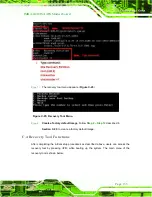
Страница 138: ...2 is hidden and the recovery tool is saved in this partition Figure C 8 Build up Recovery Partition Step 6 After completing the system configuration press any key in the following window to reboot the...

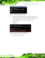
Страница 139: ...please follow the steps below Step 1 Turn on the system When the following screen displays Figure C 10 press the F3 key to access the recovery tool The message will display for 10 seconds please press...

Страница 140: ...ATX Motherboard Figure C 12 About Symantec Ghost Window Step 4 Use mouse to navigate to the option shown below Figure C 13 Figure C 13 Symantec Ghost Path Step 5 Select the local source drive Drive 1...

Страница 141: ...ve as shown in Figure C 15 Then click OK Figure C 15 Select a Source Partition from Basic Drive Step 7 Select 1 2 Recovery NTFS drive and enter a file name called iei Figure C 16 Click Save The factor...

Страница 142: ...2164 Page 128 IMBA G412ISA ATX Motherboard Figure C 16 File Name to Copy Image to Step 8 When the Compress Image screen in Figure C 17 prompts click High to make the image file smaller Figure C 17 Com...

Страница 143: ...e Figure C 18 Image Creation Confirmation Step 10 The Symantec Ghost starts to create the factory default image Figure C 19 Figure C 19 Image Creation Complete Step 11 When the image creation complete...

Страница 144: ...oft Windows Please follow the steps below to setup recovery tool for Linux OS Step 1 Hardware and BIOS setup Refer to Section C 2 1 Step 2 Install Linux operating system Make sure to install GRUB v0 9...

Страница 145: ...diskpart DISKPART list vol DISKPART sel disk 0 DISKPART create part pri size ___ DISKPART assign letter N DISKPART exit system32 format N fs ntfs q v Recovery y system32 exit Step 4 Build up recovery...

Страница 146: ...s the recovery tool main menu by modifying the menu lst To first access the recovery tool main menu the menu lst must be modified In Linux system enter Administrator root When prompt appears type cd b...

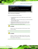
Страница 147: ...ep 8 Create a factory default image Follow Step 2 Step 12 described in Section C 2 5 to create a factory default image C 4 Recovery Tool Functions After completing the initial setup procedures as desc...

Страница 148: ...will be saved in the hidden partition 8 Restore your last backup Restore the last system backup image 9 Manual Enter the Symantec Ghost window to configure manually 10 Quit Exit the recovery tool and...

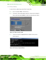
Страница 149: ...press Enter in the main menu Step 2 The Symantec Ghost window appears and starts to restore the factory default A factory default image called iei GHO is created in the hidden Recovery partition Figu...

Страница 150: ...ter in the main menu Step 2 The Symantec Ghost window appears and starts to backup the system A backup image called iei_user GHO is created in the hidden Recovery partition Figure C 29 Backup System S...

Страница 151: ...ps below Step 1 Type 3 and press Enter in the main menu Step 2 The Symantec Ghost window appears and starts to restore the last backup image iei_user GHO Figure C 31 Restore Backup Step 3 The screen i...

Страница 152: ...lease follow the steps below Step 1 Type 4 and press Enter in the main menu Step 2 The Symantec Ghost window appears Use the Ghost program to backup or recover the system manually Figure C 33 Symantec...

Страница 153: ...fore using one key recovery Please follow the steps below to install the SATA RAID AHCI driver Step 1 Copy the SATA RAID AHCI driver to a floppy disk and insert the floppy disk into a USB floppy disk...

Страница 154: ...TX Motherboard Step 5 When the following window appears press S to select Specify Additional Device Step 6 In the following window select a SATA controller mode used in the system Then press Enter The...

Страница 155: ...re from Step 4 in Section C 2 2 Create Partitions to finish the whole setup process S t e p 0 C 5 2 Sys tem Memory Requirement To be able to access the recovery tool by pressing F3 while booting up th...

Страница 156: ...1421 20 2012164 Page 142 IMBA G412ISA ATX Motherboard Appendix D D Watchdog Timer...

Страница 157: ...g Timer INT 15H AH 6FH Sub function AL 2 Sets the Watchdog Timer s period BL Time out value Its unit second is dependent on the item Watchdog Timer unit select in CMOS setup Table D 1 AH 6FH Sub funct...

Страница 158: ...dog Timer is not deactivated the system will automatically restart after the Timer has finished its countdown EXAMPLE PROGRAM INITIAL TIMER PERIOD COUNTER W_LOOP MOV AX 6F02H setting the time out valu...

Страница 159: ...2012 1 202012 1 20 IMBA G412ISA ATX Motherboard Page 145 Appendix E E Digital I O Interface...

Страница 160: ...bit4 bit7 as Input value mov dx 0A21h GPIO output I O base address in al dx Get output status jmp 2 Wait jmp 2 Wait and al 0Fh mov bl al Move al to bl temporarily inc dx sets dx to 0A22h in al dx Get...

Страница 161: ...2012 1 202012 1 20 IMBA G412ISA ATX Motherboard Page 147 Appendix F F Hazardous Materials Dis clos ure...

Страница 162: ...owledges the presences of small quantities of certain materials in the product and is applicable to China RoHS only A label will be placed on each product to indicate the estimated Environmentally Fri...

Страница 163: ...nted Circuit Board X O O O O X Metal Fas teners X O O O O O Cable As s embly X O O O O X Fan As s embly X O O O O X Power Supply As s emblies X O O O O X Battery O O O O O O O This toxic or hazardous...

Страница 164: ...012164 Page 150 IMBA G412ISA ATX Motherboard RoHS RoHS Pb Hg Cd CR VI PBB PBDE X O O O O X X O O O O X X O O O O X X O O O O O X O O O O X X O O O O X X O O O O X O O O O O O O SJ T11363 2006 X SJ T11...

Отзывы: