background image


IKARPC-W10A-BT In-vehicle Panel PC

Page 24 

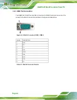
3.6.3 OBD-II Connection 

The IKARPC-W10A-BT has one DB-9 connector for OBD-II/CAN-bus connection. The 

pinouts for the OBD-II connector are listed in the figure and table below. 


Figure 3-8: OBD-II Connector 


PIN NO. 

DESCRIPTION 

1 GND 

2 GND 

3 OBD-CAN_H 

4 ISO-9141-2-K 

5 OBD-CAN_L 

6 J1850- 

7 J1850+ 

8 ISO-9141-2-L 

9 NC 

Table 3-3: OBD-II Connector Pinouts 

Содержание IKARPC-W10A-BT

Страница 1: ...icle Panel PC Page I User Manual MODEL IKARPC W10A BT 10 1 In Vehicle Panel PC with Touchscreen Intel Atom Processor E3826 OBD II GPS USB 2 0 3 0 HDMI RS 232 422 485 RoHS Compliant IP 64 Front Panel R...

Страница 2: ...IKARPC W10A BT In vehicle Panel PC Page II Revision Date Version Changes July 23 2015 1 01 Added a SD card compatibility issue notice April 28 2015 1 00 Initial release...

Страница 3: ...damages arising out of the use or inability to use the product or documentation even if advised of the possibility of such damages This document contains proprietary information protected by copyright...

Страница 4: ...CAUTION Cautionary messages should be heeded to help reduce the chance of losing data or damaging the product NOTE These messages inform the reader of essential but non critical information These mes...

Страница 5: ...CKING 11 2 1 PACKING LIST 12 2 2 OPTIONAL ITEMS 13 3 INSTALLATION 16 3 1 ANTI STATIC PRECAUTIONS 17 3 2 INSTALLATION PRECAUTIONS 17 3 3 SD CARD INSTALLATION 18 3 4 SIM CARD INSTALLATION 19 3 5 MOUNTIN...

Страница 6: ...figuration 42 5 3 2 1 Serial Port n Configuration 42 5 3 3 Hardware Monitor 46 5 3 4 Power Management 47 5 3 5 SMS RTC Wake Settings 49 5 3 6 Serial Port Console Redirection 50 5 3 7 CPU Configuration...

Страница 7: ...e MINI_PCIE2 73 6 2 11 PCIe Mini Socket MINI_PCIE3 74 6 2 12 Programming Connector JMCU1 75 6 2 13 Programming Connector JOBD1 75 6 2 14 Speaker Connector JSP1 75 6 2 15 Touch Panel Connector TOUCH1 7...

Страница 8: ...nstall SIM Card 20 Figure 3 5 VESA Mount Retention Screw Holes 21 Figure 3 6 RS 232 Connector COM1 COM2 22 Figure 3 7 GPIO and RS 422 485 Connector 23 Figure 3 8 OBD II Connector 24 Figure 3 9 OBD II...

Страница 9: ...69 Table 6 3 BIOS Flash Connector JSPI1 Pinouts 69 Table 6 4 Camera Connector WEB1 Pinouts 69 Table 6 5 Clear CMOS Connector C_CMOS1 Pinouts 70 Table 6 6 Debug Port Connector DBG_PORT1 Pinouts 70 Tabl...

Страница 10: ......

Страница 11: ...IKARPC W10A BT In vehicle Panel PC Page 1 Chapter 1 1 Introduction...

Страница 12: ...RPC W10A BT an ideal system for in vehicle applications Two serial ports one GPIO and RS 422 485 port one external USB 3 0 port and one external USB 2 0 port ensure simplified connectivity to a variet...

Страница 13: ...panel RoHS compliance 1 3 Front Panel The front of the IKARPC W10A BT is a flat panel screen with a plastic frame The components on the front panel are listed below 2 megapixel camera Ambient light se...

Страница 14: ...ed Blue The system is turned on At regular intervals low voltage warning configured by BIOS option Section 5 3 4 Power LED Blinking At irregular intervals long short short GPS antenna is not connected...

Страница 15: ...ess panel Figure 1 4 Rear Panel 1 5 Bottom Panel The following I O connectors can be found on the bottom panel 1 x 9 V 30 V power input connector 1 x GbE LAN connector 1 x HDMI port 1 x OBD II CAN bus...

Страница 16: ...Page 6 Figure 1 5 Bottom View 1 6 Right Side Panel The right side panel provides access to the following I O connectors 1 x Audio line out jack 1 x Audio mic in jack 1 x USB 2 0 connector 1 x SD card...

Страница 17: ...nstalled 2 GB DDR3 SDRAM memory Audio One 2 W speaker Camera 2 megapixel front facing camera Watchdog Timer Software programmable supports 1 255 sec system reset Real time Clock Battery backup RTC Sto...

Страница 18: ...ith software configurable delay time Physical Character Construction Material ABS PC plastic Mounting VESA 100 mm x 100 mm Dimensions W x H x D 277 mm x 186 mm x 27 mm Operation Temperature 10 C 60 C...

Страница 19: ...ial ports 1 x RS 422 485 serial port and GPIO 4 bit input 4 bit output 1 x USB 3 0 Side Panel 1 x Audio line out 1 x Audio mic in 1 x SD card slot 1 x USB 2 0 Button 1 x Power button LED Indicators 1...

Страница 20: ...IKARPC W10A BT In vehicle Panel PC Page 10 1 9 Dimensions The dimensions are shown below Figure 1 8 Dimensions unit mm...

Страница 21: ...IKARPC W10A BT In vehicle Panel PC Page 11 Chapter 2 2 Unpacking...

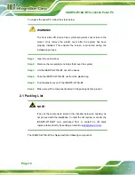
Страница 22: ...er the system Step 3 Lift the IKARPC W10A BT out of the boxes Step 4 Take the IKARPC W10A BT out from the plastic bag Step 5 Pull the plastic cover off the IKARPC W10A BT Step 6 Make sure all the comp...

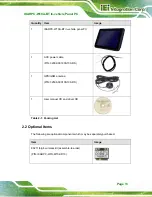
Страница 23: ...power cable P N 32002 001900 100 RS 1 GPS GSM antenna P N 32506 000100 100 RS 1 User manual CD and driver CD Table 2 1 Packing List 2 2 Optional Items The following are optional components which may...

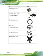
Страница 24: ...emble to order P N IKARPC 3G KIT02 R10 Power adapter with transfer cable P N IVIPOWER 4PIN R10 Cigarette lighter power cable P N 32002 004000 100 RS OBD II cable P N 32025 000300 100 RS J1939 FMS cabl...

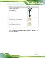
Страница 25: ...unt stand 286 mm P N IVI MK02 R10 Windows Embedded 7 CD P N IKARPC W10A BT WES7P R10 Windows Embedded 8 CD P N IKARPC W10A WE8S R10 Table 2 2 Optional Items If any of these items are missing or damage...

Страница 26: ...IKARPC W10A BT In vehicle Panel PC Page 16 Chapter 3 3 Installation...

Страница 27: ...can help to prevent ESD from damaging the board Self grounding Before handling the board touch any grounded conducting material During the time the board is handled frequently touch any conducting ma...

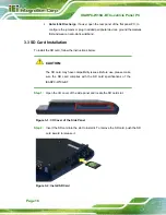
Страница 28: ...To install the SD card follow the instructions below CAUTION The SD card may have compatibility issues Before use please make sure the SD card complies with the SD card specifications of the IKARPC W...

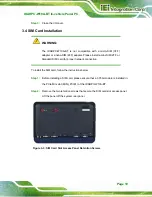
Страница 29: ...M 2FF or Standard SIM card for proper network connection To install the SIM card follow the instructions below Step 1 Before installing a SIM card please ensure that a 3 75G module is installed in the...

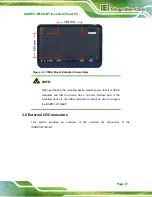
Страница 30: ...tep 0 NOTE IEI provides an application tool Mobile AP for users to switch between SIM 1 and SIM2 Please refer to Section 4 3 for more detail 3 5 Mounting the System The IKARPC W10A BT is VESA Video El...

Страница 31: ...mounting device please ensure that it is VESA compliant and that the device has a 100 mm interface pad If the mounting device is not VESA compliant it cannot be used to support the IKARPC W10A BT 3 6...

Страница 32: ...BT has two DB 9 connectors for RS 232 serial port connection The pinouts for the RS 232 connectors are listed in the figure and table below Figure 3 6 RS 232 Connector COM1 COM2 PIN NO DESCRIPTION 1...

Страница 33: ...on The pinouts for the GPIO and RS 422 485 connector are listed in the figure and table below Figure 3 7 GPIO and RS 422 485 Connector PIN NO DESCRIPTION PIN NO DESCRIPTION 1 DIN0 9 DOUT3 2 DIN1 10 GN...

Страница 34: ...DB 9 connector for OBD II CAN bus connection The pinouts for the OBD II connector are listed in the figure and table below Figure 3 8 OBD II Connector PIN NO DESCRIPTION 1 GND 2 GND 3 OBD CAN_H 4 ISO...

Страница 35: ...arately The user can use these cables to connect the IKARPC W10A BT with the vehicle OBD II Cable J1939 FMS Cable Figure 3 9 OBD II Cable and J1939 FMS Cable The pinout locations of OBD II cable conne...

Страница 36: ...connector are listed in the figure and table below Figure 3 12 Power Input Connector PIN NO DESCRIPTION 1 GND 2 GND 3 BATTERY 4 ACCON Table 3 4 Power Input Connector Pinouts The IKARPC W10A BT can use...

Страница 37: ...ut voltage is being fed into the system Incorrect voltages applied to the system may cause damage to the internal electronic components and may also cause injury to the user To power on the IKARPC W10...

Страница 38: ...V Standby Power Off On after 1 second On On Auto Start up After 10 60 seconds selectable Auto Shut down After 10 180 secs selectable Table 3 5 Power State and Ignition System 3 8 System Maintenance I...

Страница 39: ...IKARPC W10A BT In vehicle Panel PC Page 29 Chapter 4 4 Software Installation...

Страница 40: ...All the utilities for the IKARPC W10A BT are on the CD that came with the system To install the drivers or utilities please follow the steps below Step 1 Insert the CD into a CD drive connected to th...

Страница 41: ...ows 7 and Windows 8 operating systems Please select the corresponding drivers for the system The following drivers can be installed on the Windows 7 operating system Chipset Graphics Audio LAN WLAN o...

Страница 42: ...W10A BT with 3 75G module installed to manage mobile network and make a phone call 4 3 1 Installation To install this application tool please locate the following folder in the utility CD x iKarPC W10...

Страница 43: ...tion Sim card switch Tap a SIM card to designate a SIM card to use or tap the Refresh SIM status button to let the system detect automatically Network Connection o Status shows the connection status T...

Страница 44: ...3 The functions are described below Figure 4 3 Mobile AP Dial Up Tap to delete the previously entered number Dial Tap to place a phone call after entering the phone number Hang Up Tap to end a phone...

Страница 45: ...IKARPC W10A BT In vehicle Panel PC Page 35 Chapter 5 5 BIOS...

Страница 46: ...ivated in one of two ways 1 Press the DEL or F2 key as soon as the system is turned on or 2 Press the DEL or F2 key when the Press DEL or F2 to enter SETUP message appears on the screen If the message...

Страница 47: ...F3 Load optimized defaults F4 Save changes and Exit BIOS Table 5 1 BIOS Navigation Keys 5 1 3 Getting Help When F1 is pressed a small help window describing the appropriate keys to use and the possibl...

Страница 48: ...iguration Microcode Patch 901 BayTrial SoC D0 Stepping Memory Information Total Memory 2048 MB LPDDR3 TXE Information Sec RC Version 00 05 00 00 TXE FW Version 01 00 02 1060 System Date Fri 01 23 2015...

Страница 49: ...formation lists the total memory of the system TXE Information The TXE Information lists a brief summary of Intel Trusted Execution Engine TXE The fields in TXE Information cannot be changed The items...

Страница 50: ...ity Copyright C 2015 American Megatrends Inc Main Advanced Chipset Security Boot Save Exit ACPI Settings Super IO Configuration Hardware Monitor Power Management SMS RTC Wake Settings Serial Port Cons...

Страница 51: ...SUSPEND button is pressed Select Screen Select Item EnterSelect Change Opt F1 General Help F2 Previous Values F3 Optimized Defaults F4 Save Exit ESC Exit Version 2 11 1210 Copyright C 2011 American Me...

Страница 52: ...us Values F3 Optimized Defaults F4 Save Exit ESC Exit Version 2 17 1245 Copyright C 2015 American Megatrends Inc BIOS Menu 4 Super IO Configuration 5 3 2 1 Serial Port n Configuration Use the Serial P...

Страница 53: ...address are automatically detected IO 3F8h IRQ 4 Serial Port I O port address is 3F8h and the interrupt address is IRQ4 IO 3F8h IRQ 3 4 5 6 7 9 10 11 12 Serial Port I O port address is 3F8h and the in...

Страница 54: ...address are automatically detected IO 2F8h IRQ 3 Serial Port I O port address is 2F8h and the interrupt address is IRQ3 IO 3F8h IRQ 3 4 5 6 7 9 10 11 12 Serial Port I O port address is 3F8h and the in...

Страница 55: ...ddress are automatically detected IO 2E0h IRQ 11 Serial Port I O port address is 2E0h and the interrupt address is IRQ11 IO 3F8h IRQ 3 4 5 6 7 9 10 11 12 Serial Port I O port address is 3F8h and the i...

Страница 56: ...tio Setup Utility Copyright C 2015 American Megatrends Inc Advanced PC Health Status CPU Temperature 36 C System Temperature 34 C SOC_VCC 0 808 V V5S 5 107 V 12S 12 563 V 1 5S 1 513 V VCC3V 3 312 V VS...

Страница 57: ...On Delay 10 sec Auto Power Off Delay 20 sec Set Low Voltage Warning 8V 37V Select Screen Select Item Enter Select Change Opt F1 General Help F2 Previous Values F3 Optimized Defaults F4 Save Exit ESC E...

Страница 58: ...ower on delay time Configuration options are listed below 10 sec DEFAULT 30 sec 1 min 5 min 10 min 15 min 30 min 1 hour Auto Power Off Delay 20 sec Use the Auto Power Off Delay option to set the autom...

Страница 59: ...eral Help F2 Previous Values F3 Optimized Defaults F4 Save Exit ESC Exit Version 2 17 1245 Copyright C 2015 American Megatrends Inc BIOS Menu 8 SMS RTC Wake Settings Wake system with SMS Disabled Use...

Страница 60: ...9 allows the console redirection options to be configured Console redirection allows users to maintain a system remotely by re directing keyboard input and text output through the serial port Aptio S...

Страница 61: ...type is VT UTF8 ANSI DEFAULT The target terminal type is ANSI Bits per second 115200 Use the Bits per second option to specify the serial port transmission speed The speed must match the other side Lo...

Страница 62: ...even Odd The parity bit is 0 if the number of ones in the data bits is odd Mark The parity bit is always 1 This option does not provide error detection Space The parity bit is always 0 This option do...

Страница 63: ...echnology Select Screen Select Item Enter Select Change Opt F1 General Help F2 Previous Values F3 Optimized Defaults F4 Save Exit ESC Exit Version 2 17 1245 Copyright C 2015 American Megatrends Inc BI...

Страница 64: ...to enable or disable virtualization on the system When combined with third party software Intel Virtualization technology allows several OSs to run on the same system at the same time Disabled DEFAUL...

Страница 65: ...Item Enter Select Change Opt F1 General Help F2 Previous Values F3 Optimized Defaults F4 Save Exit ESC Exit Version 2 17 1245 Copyright C 2015 American Megatrends Inc BIOS Menu 11 IDE Configuration Se...

Страница 66: ...F1 General Help F2 Previous Values F3 Optimized Defaults F4 Save Exit ESC Exit Version 2 17 1245 Copyright C 2015 American Megatrends Inc BIOS Menu 12 USB Configuration Legacy USB Support Enabled Use...

Страница 67: ...he Chipset BIOS menu may cause the system to malfunction Aptio Setup Utility Copyright C 2015 American Megatrends Inc Main Advanced Chipset Security Boot Save Exit North Bridge South Bridge Host Bridg...

Страница 68: ...2015 American Megatrends Inc Chipset Intel IGD Configuration Memory Information Total Memory 2048 MB LPDDR3 DIMM1 2048 MB LPDDR3 DIMM2 Not Present Config Intel IGD Settings Select Screen Select Item E...

Страница 69: ...l Graphics Device Select Screen Select Item EnterSelect Change Opt F1 General Help F2 Previous Values F3 Optimized Defaults F4 Save Exit ESC Exit Version 2 17 1245 Copyright C 2015 American Megatrends...

Страница 70: ...ng function is disabled 5 4 2 South Bridge Configuration Use the South Bridge menu BIOS Menu 16 to configure the audio device connected to the system Aptio Setup Utility Copyright C 2015 American Mega...

Страница 71: ...ecurity Use the Security menu BIOS Menu 17 to set system and user passwords Aptio Setup Utility Copyright C 2015 American Megatrends Inc Main Advanced Chipset Security Boot Save Exit Password Descript...

Страница 72: ...abled Option ROM Messages Force BIOS Select the keyboard NumLock state Select Screen Select Item Enter Select Change Opt F1 General Help F2 Previous Values F3 Optimized Defaults F4 Save Exit ESC Exit...

Страница 73: ...ssages displayed Enabled DEFAULT OEM Logo displayed instead of POST messages UEFI Boot Disabled Use the UEFI Boot BIOS option to allow the system to boot from the UEFI devices Enabled Enables to boot...

Страница 74: ...aults Save as User Defaults Restore User Defaults Reset the system after saving the changes Select Screen Select Item Enter Select Change Opt F1 General Help F2 Previous Values F3 Optimized Defaults F...

Страница 75: ...ult values for each of the parameters on the Setup menus F3 key can be used for this operation Save as User Defaults Use the Save as User Defaults option to save the changes done so far as user defaul...

Страница 76: ...IKARPC W10A BT In vehicle Panel PC Page 66 Chapter 6 6 Interface Connectors...

Страница 77: ...nnectors and configuration jumpers The connector locations are shown in Figure 6 1 and Figure 6 2 The Pin 1 locations of the on board connectors are also indicated in the diagrams below The connector...

Страница 78: ...afer WEB1 Clear CMOS connector 2 pin header C_CMOS1 DDR3 SO DIMM socket 204 pin SO DIMM socket DIMM1 Debug port connector 12 pin wafer DBG_PORT1 GPS antenna connector Antenna connector ANT1 LED connec...

Страница 79: ...ce Connectors 6 2 1 Battery Connector BT1 PIN NO DESCRIPTION 1 VBATT 2 GND Table 6 2 Battery Connector BT1 Pinouts 6 2 2 BIOS Flash Connector JSPI1 PIN NO DESCRIPTION 1 VCC3 2 CS 3 MISO 4 CLK 5 MOSI 6...

Страница 80: ...MOS1 Pinouts 6 2 5 Debug Port Connector DBG_PORT1 PIN NO DESCRIPTION 1 GND 2 CLK33M 3 RESET 4 FRAME 5 LAD0 6 LAD1 7 LAD2 8 LAD3 9 SERIRQ 10 GND 11 VCC3 12 N A Table 6 6 Debug Port Connector DBG_PORT1...

Страница 81: ...GND 3 NC 23 NC 4 NC 24 NC 5 NC 25 GND 6 NC 26 NC 7 GND 27 NC 8 LCM_RIN0 28 NC 9 LCM_RIN0 29 VCC_LCD_AVDD 10 GND 30 GND 11 LCM_RIN1 31 LCM_LEDK 12 LCM_RIN1 32 LCM_LEDK 13 GND 33 NC 14 LCM_RIN2 34 NC 1...

Страница 82: ...PIN NO DESCRIPTION PIN NO DESCRIPTION 1 NC 2 VCC3 3 NC 4 GND 5 NC 6 VCC1 5 7 NC 8 SIM_VCC 9 GND 10 SIM_CIO 11 NC 12 SIM_CLK 13 NC 14 SIM_RST 15 GND 16 NC 17 NC 18 GND 19 NC 20 NC 21 GND 22 NC 23 NC 2...

Страница 83: ...e PIN NO DESCRIPTION PIN NO DESCRIPTION 1 WAKE 2 VCC3 3 NC 4 GND 5 NC 6 VCC1 5 7 NC 8 NC 9 GND 10 NC 11 CLK_PCIE_CLK_N 12 NC 13 CLK_PCIE_CLK_P 14 NC 15 GND 16 NC 17 NC 18 GND 19 NC 20 GPIO_WIFI 21 WIF...

Страница 84: ...ini modules can be installed into this socket PIN NO DESCRIPTION PIN NO DESCRIPTION 1 WAKE 2 VCC3 3 NC 4 GND 5 NC 6 VCC1 5 7 NC 8 SIM_VCC 9 GND 10 SIM_CIO 11 CLK_PCIE_CLK_N 12 SIM_CLK 13 CLK_PCIE_CLK_...

Страница 85: ...tor JMCU1 PIN NO DESCRIPTION 1 MCLR 2 VCC5 3 GND 4 ICSP_CLK 5 ICSP_DAT Table 6 13 Programming Connector JMCU1 Pinouts 6 2 13 Programming Connector JOBD1 PIN NO DESCRIPTION 1 MCLR 2 VCC5 3 GND 4 ICSP_C...

Страница 86: ...IKARPC W10A BT In vehicle Panel PC Page 76 6 2 15 Touch Panel Connector TOUCH1 PIN NO DESCRIPTION 1 GND 2 GND 3 USB 4 USB 5 VCC 6 VCC Table 6 16 Touch Panel Connector TOUCH1 Pinouts...

Страница 87: ...IKARPC W10A BT In vehicle Panel PC Page 77 Appendix A A Regulatory Compliance...

Страница 88: ...liance with the essential requirements and other relevant provisions of Directive 1999 5 EC Bulgarian IEI Integration Corp 1999 5 esky Czech IEI Integration Corp t mto prohla uje e tento za zen je ve...

Страница 89: ...9 5 EK Lietuvi Lithuanian IEI Integration Corp deklaruoja kad is ranga atitinka esminius reikalavimus ir kitas 1999 5 EB Direktyvos nuostatas Nederlands Dutch IEI Integration Corp dat het toestel toes...

Страница 90: ...i dolo ili direktive 1999 5 ES Slovensky Slovak IEI Integration Corp t mto vyhlasuje e zariadenia sp a z kladn po iadavky a v etky pr slu n ustanovenia Smernice 1999 5 ES Suomi Finnish IEI Integration...

Страница 91: ...for a Class A digital device pursuant to part 15 of the FCC Rules These limits are designed to provide reasonable protection against harmful interference when the equipment is operated in a commercia...

Страница 92: ...IKARPC W10A BT In vehicle Panel PC Page 82 Appendix B B OBD II Reader Command...

Страница 93: ...13 14 15 16 17 18 19 Enter Boot Mode 0x3 1 Enter RUN Mode 0x3 0 B 2 Boot Mode Launch AP P1618QP Pic18F Bootloader Baud Rate 115200 B 3 Run Mode Any mode in Run mode AP sends query F W receives query...

Страница 94: ...3 14 15 16 17 18 19 Select a mode to send M 0 0x0 0 Ver 1 0x1 0 Ver 2 0x0 6 0x0 A 0x0 D Tele mode response M 1 0x0 0 Ver 1 0x1 0 Ver 2 0x0 6 0x0 A 0x0 D CAN S mode response M 2 0x0 0 Ver 1 0x1 0 Ver 2...

Страница 95: ...etup menu C M M1ID 1 M1ID 2 M1I D 3 M1I D 4 M1 F1I D 1 M1F 1ID 2 M1 F1I D 3 M1F 1ID 4 M1 F2I D 1 M1F 2ID 2 M1F 2ID 3 M1 F2I D 4 M2I D 1 M2I D 2 M2I D 3 M2I D 4 M2 F1I D 1 M2F 1ID 2 M2 F1I D 3 M2F1ID 4...

Страница 96: ...3 M1F 1ID 4 M1F 2ID 1 M1F 2ID 2 M1F 2ID 3 M1F 2ID 4 M2I D 1 M2I D 2 M2I D 3 M2I D 4 M2F 1ID 1 M2F 1ID 2 M2F 1ID 3 M2F 1ID 4 M2F 2ID 1 M2F 2ID 2 M2F 2ID 3 M2F 2ID 4 M3F 3ID 1 M3F 3ID 2 M3F 3ID 3 M3F 3...

Страница 97: ...13 14 15 16 17 18 19 Scan all Z 0 0x0 D Scan all Z 0x0 D Scan OBD II Z 1 0x0 D Scan J1939 Z 2 0x0 D Scan FMS Z 1 0x0 D OBD II input PID 1 A Mo de 1 Mo de 2 PI D 1 PI D 2 0x0 D OBD II input PID 2 B Mo...

Страница 98: ...Page 88 Reserved H J1939 input PSPF I P 1 P 2 P 1 P 2 0x0 D FMS input PSPF J P 1 P 2 P 1 P 2 0x0 D Version Y 0x0 D F W returns after receiving query 1 2 3 4 5 6 7 8 9 10 11 12 13 14 15 16 17 18 19 No...

Страница 99: ...code as the input format of the firmware ID number Key in value ID Len Data Other Information Data include eight different bytes Byte 1 Data include some return information For example 1 18DAF110 08...

Страница 100: ...me with the PID code table on Wikipedia Byte 7 define as D same with the PID code table on Wikipedia As shown below Example 2 To Scan Input Z CR Use ASCII code as the input format of the firmware Outp...

Страница 101: ...IKARPC W10A BT In vehicle Panel PC Page 91 Appendix C C Watchdog Timer...

Страница 102: ...INT 15H AH 6FH Sub function AL 2 Sets the Watchdog Timer s period BL Time out value Its unit second is dependent on the item Watchdog Timer unit select in CMOS setup Table C 1 AH 6FH Sub function Cal...

Страница 103: ...mer is not deactivated the system will automatically restart after the Timer has finished its countdown EXAMPLE PROGRAM INITIAL TIMER PERIOD COUNTER W_LOOP MOV AX 6F02H setting the time out value MOV...

Страница 104: ...IKARPC W10A BT In vehicle Panel PC Page 94 Appendix D D Hazardous Materials Disclosure...

Страница 105: ...s the presences of small quantities of certain materials in the product and is applicable to China RoHS only A label will be placed on each product to indicate the estimated Environmentally Friendly U...

Страница 106: ...Circuit Board O O O O O O Metal Fasteners O O O O O O Cable Assembly O O O O O O Fan Assembly O O O O O O Power Supply Assemblies O O O O O O Battery O O O O O O O This toxic or hazardous substance is...

Страница 107: ...RPC W10A BT In vehicle Panel PC Page 97 RoHS RoHS Pb Hg Cd CR VI PBB PBDE O O O O O O O O O O O O O O O O O O O O O O O O O O O O O O O O O O O O O O O O O O O O O O O O O SJ T11363 2006 X SJ T11363 2...

Отзывы: