


FLEX-BX100-ULT5
Page 28
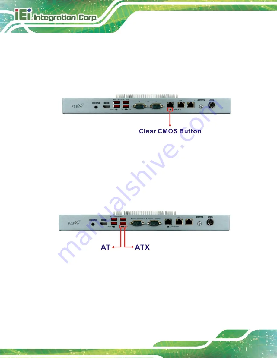
3.10 Clear CMOS
If the FLEX-BX100-ULT5 fails to boot due to improper BIOS settings, the clear CMOS
jumper clears the CMOS data and resets the system BIOS information. To do this, push
the clear CMOS button for three seconds, then restart the system. The clear CMOS button
location is shown in
Figure 3-21: Clear CMOS Button Location
3.11 AT/ATX Mode Selection
AT or ATX power mode can be used on the FLEX-BX100-ULT5. The selection is made
through an AT/ATX switch located on the front panel (
Figure 3-22: AT/ATX Switch Location
Содержание FLEX-BX100-ULT5
Страница 2: ...FLEX BX100 ULT5 Page ii Revision Date Version Changes January 14 2021 1 00 Initial release...
Страница 12: ...FLEX BX100 ULT5 Page xii Figure 6 1 Main Board Layout Diagram 73...
Страница 15: ...FLEX BX100 ULT5 Page 1 Chapter 1 1 Introduction...
Страница 23: ...FLEX BX100 ULT5 Page 9 Chapter 2 2 Unpacking...
Страница 27: ...FLEX BX100 ULT5 Page 13 Chapter 3 3 Installation...
Страница 47: ...FLEX BX100 ULT5 Page 33 Chapter 4 4 BIOS...
Страница 82: ...FLEX BX100 ULT5 Page 68 Chapter 5 5 Troubleshooting and Maintenance...
Страница 86: ...FLEX BX100 ULT5 Page 72 6 Interface Connectors Chapter 6...
Страница 100: ...FLEX BX100 ULT5 Page 86 Appendix A A Regulatory Compliance...
Страница 105: ...FLEX BX100 ULT5 Page 91 B Safety Precautions Appendix B...
Страница 111: ...FLEX BX100 ULT5 Page 97 Appendix C C BIOS Menu Options...
Страница 114: ...FLEX BX100 ULT5 Page 100 Appendix D D Watchdog Timer...
Страница 117: ...FLEX BX100 ULT5 Page 103 Appendix E E Error Beep Code...
Страница 119: ...FLEX BX100 ULT5 Page 105 Appendix F F Hazardous Materials Disclosure...