background image


E-265-910/EP-267-910 Enrich POS System

Page 104 


Programmable digital I/O 


System health configuration save and load 

7.2 COM Port LED Indicators 

The four COM port connectors each have two LED indicators. LED status indicators are 

described in below. 


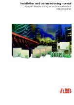
A red LED indicates the pin-9 signal on the COM port is 

12 V power signal. 


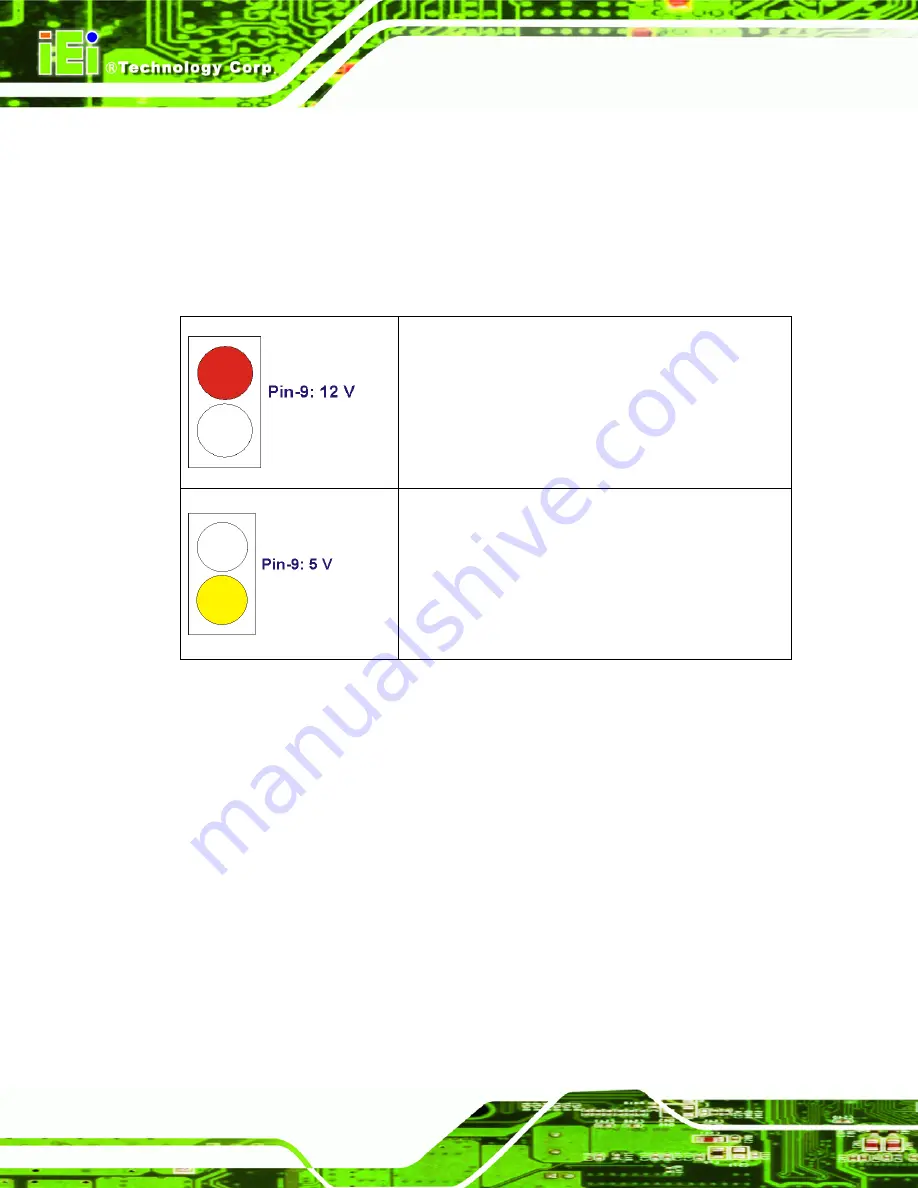
A yellow LED indicates the pin-9 signal on the COM port 

is 5 V power signal. 


Содержание EP-265-910

Страница 1: ...EP 265 910 EP 267 910 Enrich POS System Page i EP 265 910 EP 267 910 Enrich POS System ...

Страница 2: ...E 265 910 EP 267 910 Enrich POS System Page ii Revision Date Version Changes 2008 11 1 01 Added current rating of the 12 V output connector and PoweredUSB connectors 2008 08 1 00 Initial release ...

Страница 3: ...al damages arising out of the use or inability to use the product or documentation even if advised of the possibility of such damages This document contains proprietary information protected by copyright All rights are reserved No part of this manual may be reproduced by any mechanical electronic or other means in any form without prior written permission of the manufacturer TRADEMARKS All registe...

Страница 4: ...ng message A warning message is shown below WARNING This is an example of a warning message Failure to adhere to warning messages may result in permanent damage to the EP series or personal injury to the user Please take warning messages seriously CAUTION Cautionary messages should also be heeded to help reduce the chance of losing data or damaging the EP series Cautions are easy to recognize The ...

Страница 5: ... critical information These messages should be read carefully as any directions or instructions contained therein can help avoid making mistakes Notes are easy to recognize The word note is written as NOTE both capitalized and bold and is followed by text The text is the cautionary message A note message is shown below NOTE This is an example of a note message Notes should always be read Notes con...

Страница 6: ...d the EP series from or contact an IEI sales representative directly To contact an IEI sales representative please send an email to sales iei com tw The items listed below should all be included in the EP 265 910 EP 267 910 series package 1 x EP 265 910 EP 267 910 POS system 1 x Screw set 1 x Power cord 1 x Power supply 1 x Touch pen 1 x User Manual and driver CD Images of the above items are show...

Страница 7: ...el 8 1 3 SPECIFICATIONS 8 1 3 1 Preinstalled Hardware Components 8 1 3 2 System Specifications 9 2 DETAILED SPECIFICATIONS 12 2 1 DIMENSIONS 13 2 1 1 EP 265 910 Dimensions 13 2 1 2 EP 267 910 Dimensions 14 2 2 INTEL CELERON M PROCESSOR SUPPORT 14 2 3 MOTHERBOARD COMPONENTS 15 2 3 1 Memory Support 15 2 3 1 1 Installed Memory 15 2 3 1 2 Additional Memory 15 2 3 2 Storage Capacity 16 2 4 EXTERNAL PER...

Страница 8: ... Mode 23 2 8 1 1 AT Power Mode 24 2 8 1 2 ATX Power Mode 24 2 8 2 Power Supply 24 2 8 3 Power Connectors 24 2 8 3 1 Power Input Connector 25 2 8 3 2 Power Output Connector 25 2 8 4 RJ 12 Connectors for Cash Drawer Power 25 2 9 WIRELESS ETHERNET 26 2 10 THERMAL MANAGEMENT 26 3 UNPACKING 27 3 1 UNPACKING 28 3 1 1 Packing List 29 4 INSTALLATION 30 4 1 ANTI STATIC PRECAUTIONS 31 4 2 INSTALLATION PRECA...

Страница 9: ...0 4 USB Device Connection 49 4 10 5 Parallel Device Connection 50 5 SYSTEM MAINTENANCE 52 5 1 SYSTEM MAINTENANCE INTRODUCTION 53 5 2 ANTI STATIC PRECAUTIONS 53 5 3 TURN OFF THE POWER 54 5 4 REPLACING COMPONENTS 54 5 4 1 Hard Disk Drive Replacement 54 5 4 2 CF Card Replacement 54 5 4 3 DIMM Module Replacement 55 5 4 4 Wireless Module Replacement 56 5 4 5 Motherboard Replacement 57 6 AMI BIOS SETUP ...

Страница 10: ...ration 93 6 7 2 Southbridge Configuration 96 6 8 POWER 97 6 8 1 Advanced Power Configuration 98 6 9 EXIT 100 7 SYSTEM MONITORING 102 7 1 IEI INTELLIGENT SYSTEM MANAGEMENT MODULE ISMM 103 7 1 1 What is iSMM 103 7 1 2 iSMM Features 103 7 2 COM PORT LED INDICATORS 104 A SYSTEM SPECIFICATIONS 105 7 3 MOTHERBOARD SPECIFICATIONS 106 A 1 PROCESSOR SPECIFICATIONS 106 A 2 SCREEN SPECIFICATIONS 107 A 3 TOUC...

Страница 11: ...recautions 116 C 2 MAINTENANCE AND CLEANING PRECAUTIONS 116 C 2 1 Maintenance and Cleaning 116 C 2 2 Cleaning Tools 117 D BIOS CONFIGURATION OPTIONS 118 D 1 BIOS CONFIGURATION OPTIONS 119 E WATCHDOG TIMER 122 F HAZARDOUS MATERIALS DISCLOSURE 125 F 1 HAZARDOUS MATERIAL DISCLOSURE TABLE FOR IPB PRODUCTS CERTIFIED AS ROHS COMPLIANT UNDER 2002 95 EC WITHOUT MERCURY 126 G INDEX 129 ...

Страница 12: ...0 Dimensions mm 14 Figure 2 3 CPU and Chipsets Heat Sink 15 Figure 2 4 Memory Module and Memory Socket 16 Figure 2 5 SATA Hard Disk Drive Bays 16 Figure 2 6 CompactFlash Slot 17 Figure 2 7 COM Ports and LED Indicators 18 Figure 2 8 RJ 45 Ethernet Connector 19 Figure 2 9 External Standard USB Ports 20 Figure 2 10 PoweredUSB Ports 20 Figure 2 11 Keyboard and Mouse Connectors 21 Figure 2 12 LCD Scree...

Страница 13: ... Voltage Select Jumper Location 42 Figure 4 12 Clear CMOS Jumper 43 Figure 4 13 COM3 COM4 and COM5 Pin 9 Setting Jumper Locations 44 Figure 4 14 I O Interface Cover Removal 45 Figure 4 15 Mounting Hole Cover Removal 45 Figure 4 16 Second Display Installation 46 Figure 4 17 Organized Second Display Cables 46 Figure 4 18 AT ATX Switch 47 Figure 4 19 LAN Connection 48 Figure 4 20 Serial Device Connec...

Страница 14: ...ifications 11 Table 4 1 Jumpers 38 Table 4 2 Preconfigured Jumpers 40 Table 4 3 Cash Drawer Voltage Select Jumper Settings 41 Table 4 4 CF Voltage Select Jumper Settings 42 Table 4 5 Clear CMOS Jumper Settings 43 Table 4 6 COM2 COM3 and COM5 Pin 9 Setting Jumper Settings 44 Table 6 1 BIOS Navigation Keys 60 ...

Страница 15: ...EP 265 910 EP 267 910 Enrich POS System Page 1 1 Introduction Chapter 1 ...

Страница 16: ...ler hub GMCH coupled with an Intel ICH6M input output controller hub ensures optimal memory graphics and peripheral I O support The system comes with 1 0 GB of preinstalled DDR2 SDRAM and supports a maximum of 2 0 GB of DDR2 SDRAM ensuring smooth data throughputs with reduced bottlenecks and fast system access Four serial ports four external USB 2 0 ports and three PoweredUSB ports ensure simplifi...

Страница 17: ...0 ports Two 12 V PoweredUSB ports and one 24 V PoweredUSB port Watchdog timer that triggers a system reset if the system hangs for some reasons iSMM system health supervision API to track the system status Built in two 3 W stereo speakers IP 64 compliant front panel AT or ATX power mode Second displays support Touch screen Fanless design RoHS comlpliance The variation of the two models is the LCD ...

Страница 18: ...ers inside the monitor rear panel The aluminum chassis consists of rear panel bottom panel and two side panels left and right The I O interface panel located on the rear panel of the EP 265 910 EP 267 910 chassis provides access to external interface connectors 1 2 2 Monitor Front Panel The front side of the EP 265 910 EP 267 910 is a flat panel TFT LCD screen surrounded by an ABS PC plastic hard ...

Страница 19: ... side panel of the EP 265 910 EP 267 910 monitor has a set of buttons to control the LCD brightness and the volume of the speakers The monitor right side panel also provides access to the I O interface panel that enables connection to a wide range of external peripheral devices Figure 1 4 Figure 1 4 EP 265 910 EP 267 910 Monitor Right Side View ...

Страница 20: ...OM port power selecting switch 12 V 5V The external I O interface connectors on the rear side of the monitor are shown in Figure 1 5 Figure 1 5 I O Interface Connectors on the Monitor Right Side Panel 1 2 4 I O Interface Panel The I O interface panel is located on the rear side of the EP 265 910 EP 267 910 chassis and protected by an easily removed cover Figure 1 6 The I O interface panel has the ...

Страница 21: ...1 x Keyboard connector 1 x Mouse connector 1 x LAN connector 2 x USB 2 0 connectors 1 x Parallel port connector 2 x RJ 12 connectors 3 x 5 V 12 V serial port connectors COM3 COM4 and COM5 1 x VGA connector The external I O interface connectors on the rear panel are shown in Figure 1 6 Figure 1 6 EP 265 910 EP 267 910 I O Interface Panel ...

Страница 22: ...wer on off Figure 1 7 Figure 1 7 EP 265 910 EP 267 910 Left Side View 1 3 Specifications 1 3 1 Preinstalled Hardware Components The EP 265 910 EP 267 910 POS system has the following preinstalled components 1 x Motherboard 1 x TFT LCD screen 1 x Touch screen 1 x Inverter 1 x Wireless LAN module 1 x DDR2 memory module 1 x AT ATX switch 2 x 3 W stereo speakers ...

Страница 23: ...024 x 768 XGA 1280 x 1024 SXGA Brightness 350 cd m2 300 cd m2 Contrast Ratio 400 1 800 1 LCD Color 262K 16 7M Pixel Pitch mm 0 297 H x 0 297 V 0 264 H x 0 264 V Viewing Angle H V 120 H 100 V 160 H 160 V Backlight MTBF 50 000 hours 50 000 hours SBC Model EPMB 9103 CPU 1 0 GHz Intel Celeron M on board Chipsets Intel 910GMLE ICH6M Memory One 1 0 GB DDR2 SDRAM DIMM pre installed Two 240 pin DIMM socke...

Страница 24: ... 47 Net weight 8 30 kg 9 80 kg IP level front panel IP 64 EMC CE EMC and FCC Safety UL and CB Touch Screen Resistive Type 5 wire touch controller IC is on board 252 W Input 90 VAC 264 VAC 50 Hz 60 Hz Power Adapter ACE D825A H RS Output 12 VDC at 4 0 A Power Consumption 66 W 1 x 12 V or 24 V DC In connector 1 x 12 V DC Out connector at 4 A 1 x AT ATX power mode switch 1 x 24 V PoweredUSB connector ...

Страница 25: ...x RJ 12 connectors 3 x 5 V 12 V serial port connectors COM3 COM4 and COM5 1 x VGA connector 1 x Serial port connector COM1 1 x 12 V PoweredUSB connector 2 x USB 2 0 connectors I O Ports and Switches Monitor Rear Panel 1 x COM1 power selecting switch Table 1 1 EP 265 910 EP 267 910 System Specifications ...

Страница 26: ...E 265 910 EP 267 910 Enrich POS System Page 12 2 Detailed Specifications Chapter 2 ...

Страница 27: ...ions provide detailed schematics and information on the dimensions of the EP 265 910 EP 267 910 2 1 1 EP 265 910 Dimensions The dimensions of the EP 265 910 are shown in Figure 2 1 and listed below Width 375 00 mm Height 392 66 mm Depth 334 64 mm Figure 2 1 EP 265 910 Dimensions mm ...

Страница 28: ...eight 414 52 mm Depth 350 47 mm Figure 2 2 EP 267 910 Dimensions mm 2 2 Intel Celeron M Processor Support A 373 Intel Celeron M processor is installed in the system The processor has a CPU speed of 1 0 GHz and a 400 MHz front side bus FSB The processor also comes with a 512 KB L2 cache The processor is protected by the dust proof heat sink shown in Figure 2 3 below ...

Страница 29: ...nts The following sections describe some of the features on the motherboard 2 3 1 Memory Support 2 3 1 1 Installed Memory One 240 pin 1 0 GB DDR2 SDRAM DIMM is installed in the EP 265 910 EP 267 910 and controlled by the Intel 910GMLE GMCH installed on the internal motherboard 2 3 1 2 Additional Memory The Intel 910GMLE is capable of supporting two 240 pin 1 0 GB max 533 MHz or 400 MHz DDR2 SDRAM ...

Страница 30: ...orage Capacity The EP 265 910 EP 267 910 comes with two hard disk drive bays for two 2 5 SATA HDDs Figure 2 5 The hard disk drive bay can be access by removing the bottom panels Figure 2 5 SATA Hard Disk Drive Bays The system can also support a CompactFlash Type II CF Type II memory disk Figure 2 6 ...

Страница 31: ... system 2 4 1 Serial Port Connectors The EP 265 910 EP 267 910 has four serial ports one on the monitor rear panel COM1 and three on the I O interface panel COM3 COM4 and COM5 Pin 9 on these four serial port DB 9 connectors can be set as either 5 V or 12 V Pin 9 settings are shown with yellow or red LED indicators next to the DB 9 CON port connectors Enabling COM devices to be powered through the ...

Страница 32: ...uthbridge The remaining four serial ports COM3 COM4 and COM5 are connected to the ICH6M LPC bus through a Fintek serial port controller 2 4 2 LAN Connectivity One of the PCI Express PCIe x1 lanes from the ICH6M Southbridge is interfaced to a Broadcom BCM5787 PCIe gigabit Ethernet GbE controller The BCM5787 is then connected directly to the RJ 45 connector on the rear panel and provides external PC...

Страница 33: ...ntegrated 10 100 1000BASE T transceiver Automatic MDI crossover function PCIe v1 0a 10 100 1000BASE T full half duplex MAC Wake on LAN support meeting the ACPI requirements Statistics for SNMP MIB II Ethernet like MIB and Ethernet MIB 802 3z clause 30 Serial EEPROM or serial flash support 2 4 3 External USB Connectors 2 4 3 1 Standard USB Connectors The EP 265 910 EP 267 910 has four USB 2 0 conne...

Страница 34: ...evices Figure 2 9 External Standard USB Ports 2 4 3 2 PoweredUSB Connectors The EP 265 910 EP 267 910 has three PoweredUSB connectors one on the monitor rear panel and two on the chassis rear panel Two of these PoweredUSB connectors provide 12 V power to the peripheral devices The remaining one PoweredUSB provides 24 V power for higher power devices Figure 2 10 PoweredUSB Ports ...

Страница 35: ...I O chipset on the motherboard that connects through the LPC bus to the Southbridge chipset Figure 2 11 Keyboard and Mouse Connectors 2 5 EP 265 910 EP 267 910 Front Side 2 5 1 Monitor A 15 or 17 LCD screen is installed in the monitor of the EP POS system The viewing angle of the IP 64 compliant front panel is adjustable The screen is shown in Figure 2 12 below Figure 2 12 LCD Screen ...

Страница 36: ... EP series 2 6 Graphics 2 6 1 Intel 910GMLE Integrated Graphics Media Accelerator 900 The Intel 910GMLE has the Intel GMA 900 integrated into the chipset and interfaced to the VGA connector on the chassis rear panel The Intel GMA 900 is a 333 MHz 256 bit graphics core and supports up to 8 5 GB s memory bandwidth Figure 2 13 VGA Connector 2 6 2 Dual Display The system supports dual display capabili...

Страница 37: ...alTek ALC262 is a four channel High Definition Audio codec with two 24 bit stereo DACs and three 20 bit stereo ADCs 2 7 2 Stereo Speakers The EP 265 910 EP 267 910 has two built in 3 W stereo speakers on the rear of the monitor Figure 2 14 Figure 2 14 Stereo Speakers 2 8 System Power 2 8 1 Power Mode The POS system can be run in the AT power mode or the ATX power mode Both these power modes are de...

Страница 38: ... via network or a power switch in standby mode Remote power control is perfect for POS applications since the POS system can be set individually and controlled remotely 2 8 2 Power Supply The system is shipped with a 100 V to 240 V IEI AC power supply unit PSU that has a maximum power output of 252 W The PSU has additional 12 V and 24 V DC output connectors The power supply is also equipped with t...

Страница 39: ...Connector A standard power inlet on the connector interface panel is provides 12 V of direct current to an external peripheral device such as a thermal printer 2 8 4 RJ 12 Connectors for Cash Drawer Power Two RJ 12 connectors on the chassis rear panel interface can provide 24 V or 12 V of power to a cash drawer The cash drawer control can be controlled through the digital I O and monitored through...

Страница 40: ... the market Figure 2 18 Wireless LAN Mini PCI Card 2 10 Thermal Management Thermal management is critical in optimizing system performance Failure to maintain proper temperature within the system may result in irreparable damage to the POS system The EP 265 910 EP 267 910 POS System is an effective heat dissipation system The heat sink on the main board works together with the heat pipe to dissipa...

Страница 41: ...EP 265 910 EP 267 910 Enrich POS System Page 27 3 Unpacking Chapter 3 ...

Страница 42: ...d during the installation process Step 1 Use box cutters a knife or a sharp pair of scissors that seals the top side of the external second box Step 2 Open the external second box Step 3 Use box cutters a knife or a sharp pair of scissors that seals the top side of the internal first box Step 4 Lift the monitor out of the boxes Step 5 Remove both polystyrene ends one from each side Step 6 Pull the...

Страница 43: ...POS system is shipped with the following components Quantity Item Image 1 EP 265 910 EP 267 910 POS system 1 Screw set 1 Power supply 1 Power cord 1 Touch pen 1 User manual CD and driver CD If any of these items are missing or damaged contact the distributor or sales representative immediately ...

Страница 44: ...E 265 910 EP 267 910 Enrich POS System Page 30 4 Installation Chapter 4 ...

Страница 45: ...d can help to prevent ESD from damaging the board Self grounding Before handling the board touch any grounded conducting material During the time the board is handled frequently touch any conducting materials that are connected to the ground Use an anti static pad When configuring the EP 265 910 EP 267 910 place it on an antic static pad This reduces the possibility of ESD damaging the EP 265 910 ...

Страница 46: ...esistive type touch screen Wireless LAN module AT ATX power switch 3 W stereo speakers Preinstalled OEM customizations may include the following Different DDR2 memory module Hard disk drive CF card Component installation is described in the following sections 4 4 Installation and Configuration Steps The following installation steps must be followed Step 1 Unpack the POS system Step 2 Install CF ca...

Страница 47: ...the bottom panels please follow the steps below Step 1 Adjust the monitor Figure 4 1 and turn the EP 265 910 EP 267 910 over to put the monitor front panel on the table Figure 4 1 Monitor Adjustment Step 2 Remove the bottom panels Remove the five retention screws Figure 4 2 from the bottom panel and lift the two bottom panels off the EP 265 910 EP 267 910 Step 0 ...

Страница 48: ...on The EP series has one CF Type II slot To install the CF card follow the instructions below Step 1 Remove the bottom panels Refer to Section 4 5 Step 2 Install the CF Card Locate the CF card socket in the chassis Correctly align the CF card with the socket and insert the CF card into the socket See Figure 4 3 ...

Страница 49: ...DD Installation The EP series has two HDD slots inside the bottom panel for two 2 5 SATA HDDs To install the HDD follow the instructions below Step 1 Remove the bottom panels Refer to Section 4 5 Step 2 Locate the HDD slot in the EP series Step 3 Remove the HDD bracket The HDD bracket is secured to the aluminum chassis by four retention screws Figure 4 4 To remove the HDD bracket please remove the...

Страница 50: ...n the four retention screw holes on the both side of the HDD with the retention screw holes of the HDD bracket Insert four retention screws into the both sides of the HDD bracket to secure the HDD to the HDD bracket See Figure 4 5 Figure 4 5 Secure the HDD with the HDD Bracket Step 6 Install the HDD Correctly align the four retention screw holes on the HDD bracket with the retention screw holes on...

Страница 51: ... a metal bridge used to close an electrical circuit It consists of two or three metal pins and a small metal clip often protected by a plastic cover that slides over the pins to connect them To CLOSE SHORT a jumper means connecting the pins of the jumper with the plastic clip and to OPEN a jumper means removing the plastic clip from a jumper Figure 4 7 Jumper Locations The following jumpers can be...

Страница 52: ...r CMOS JP3 2 pin header COM3 Pin 9 setting JP8 3 pin header COM4 Pin 9 setting JP9 3 pin header COM5 Pin 9 setting JP10 3 pin header Table 4 1 Jumpers 4 8 1 Access the Jumpers To access the jumpers please follow the steps below Step 1 Adjust the monitor and turn the EP 265 910 EP 267 910 over to put the monitor front panel on the table Step 2 Remove the bottom panels Remove the five retention scre...

Страница 53: ...n Screws Step 3 Remove the aluminum chassis The motherboard is installed inside the aluminum chassis To access the motherboard remove the four retention screws and gently lift the aluminum chassis off the EP 265 910 EP 267 910 Step 0 Figure 4 9 Motherboard Chassis Retention Screws ...

Страница 54: ... setup JP7 2 pin header LVDS voltage selection JP4 3 pin header Panel Type and Resolution JP1 8 pin header Table 4 2 Preconfigured Jumpers 4 8 3 Cash Drawer Voltage Select Jumper Label JP11 and JP12 Jumper Type 3 pin header Jumper Settings See Table 4 3 Jumper Location See Figure 4 10 Two jumpers JP11 and JP12 configure pin 4 on RJ 12 cash drawer connectors CN8 and CN9 Pin 4 on the RJ 12 cash draw...

Страница 55: ...lect Jumper Settings The Cash Drawer Voltage Select jumper locations are shown in Figure 4 10 below Figure 4 10 Cash Drawer Voltage Select Jumper Locations 4 8 4 CF Voltage Select Jumper Label JP6 Jumper Type 3 pin header Jumper Settings See Table 4 4 Jumper Location See Figure 4 11 The CF Voltage Select jumper sets the CF Type II slot can be set as either 5 V or 3 3 V CF Voltage Select jumper set...

Страница 56: ...Figure 4 11 CF Voltage Select Jumper Location 4 8 5 Clear CMOS Jumper Jumper Label JP3 Jumper Type 2 pin header Jumper Settings See Table 4 5 Jumper Location See Figure 4 12 If the EP 265 910 EP 267 910 fails to boot due to improper BIOS settings the clear CMOS jumper clears the CMOS data and resets the system BIOS information To do this use the jumper cap to close the pins for a few seconds then ...

Страница 57: ...g Enter the correct CMOS setting Load Optimal Defaults Load Failsafe Defaults After having done one of the above save the changes and exit the CMOS Setup menu The clear CMOS jumper settings are shown in Table 4 5 Clear CMOS Description OPEN Keep CMOS Setup Default SHORT Clear CMOS Setup Table 4 5 Clear CMOS Jumper Settings The location of the clear CMOS jumper is shown in Figure 4 12 below Figure ...

Страница 58: ... and the COM5 DB 9 connectors can be set as either 5 V or 12 V The COM3 COM4 and COM5 Pin 9 Setting jumper selection options are shown in Table 4 6 Short 1 2 Default Short 2 3 JP8 COM3 Pin 9 use 5 V COM3 Pin 9 use 12 V JP9 COM4 Pin 9 use 5 V COM4 Pin 9 use 12 V JP10 COM5 Pin 9 use 5 V COM5 Pin 9 use 12 V Table 4 6 COM2 COM3 and COM5 Pin 9 Setting Jumper Settings The COM3 COM4 and COM5 Pin 9 Settin...

Страница 59: ...0 EP 267 910 please follow the steps below Step 1 Remove the I O interface cover on the chassis rear panel of the EP 265 910 EP 267 910 Figure 4 14 Figure 4 14 I O Interface Cover Removal Step 2 Remove the mounting hole cover on the chassis from the rear of the EP 265 910 EP 267 910 Figure 4 15 Figure 4 15 Mounting Hole Cover Removal ...

Страница 60: ...rew holes on the mounting hole Insert the three retention screws to secure the second display to the EP 265 910 EP 267 910 Figure 4 16 Figure 4 16 Second Display Installation Step 4 Organize the second display cables and connect the connector to the connectors on the I O interface panel Figure 4 17 Figure 4 17 Organized Second Display Cables ...

Страница 61: ...ear panel Figure 4 18 Figure 4 18 AT ATX Switch Step 2 Adjust the AT ATX switch The default mode is ATX mode Figure 4 18 Step 0 4 10 2 LAN Connection There is one external RJ 45 LAN connector The RJ 45 connector enables connection to an external network To connect a LAN cable with an RJ 45 connector please follow the instructions below Step 1 Locate the RJ 45 connectors on the I O interface panel ...

Страница 62: ...tion The EP 265 910 EP 267 910 series has four male DB 9 connectors for serial devices to be connected Follow the steps below to connect a serial device to the EP 265 910 EP 267 910 series POS system Step 1 Locate the DB 9 connector The location of the DB 9 connector is shown in Chapter 2 Step 2 Insert the serial connector Insert the DB 9 connector of a serial device into the DB 9 connector on the...

Страница 63: ...Step 0 4 10 4 USB Device Connection There are four external USB 2 0 connectors All connectors are perpendicular to the EP 265 910 EP 267 910 series To connect a USB 2 0 or USB 1 1 device please follow the instructions below Step 1 Located the USB connectors The locations of the USB connectors are shown in Chapter 2 Step 2 Align the connectors Align the USB device connector with one of the connecto...

Страница 64: ...e EP 265 910 EP 267 910 has a single female DB 25 connector on the chassis rear panel for parallel devices Follow the steps below to connect a parallel device to the EP 265 910 EP 267 910 Step 1 Locate the DB 25 connector The location of the DB 25 connector is shown in Chapter 3 Step 2 Insert the DB 25 connector Insert the DB 25 connector of a parallel device into the DB 25 connector on the extern...

Страница 65: ... Enrich POS System Page 51 Figure 4 22 Parallel Device Connector Step 3 Secure the connector Secure the DB 25 connector to the external interface by tightening the two retention screws on either side of the connector Step 0 ...

Страница 66: ...E 265 910 EP 267 910 Enrich POS System Page 52 5 System Maintenance Chapter 4 ...

Страница 67: ...267 910 and severe injury to the user Electrostatic discharge ESD can cause serious damage to electronic components including the EP series Dry climates are especially susceptible to ESD It is therefore critical that whenever the EP series is accessed internally or any other electrical component is handled the following anti static precautions are strictly adhered to Wear an anti static wristband ...

Страница 68: ...f 5 4 Replacing Components 5 4 1 Hard Disk Drive Replacement If the HDD fails please follow the steps below Step 1 Follow all anti static procedures See Section 5 2 Step 2 Turn off the power See Section 5 3 Step 3 Follow the steps described in Section 4 7 to replace the HDD Step 0 5 4 2 CF Card Replacement The EP 265 910 EP 267 910 has one CF Type II slot To replace the CF card follow the instruct...

Страница 69: ...dule please follow the steps below Step 1 Follow all anti static procedures See Section 5 2 Step 2 Turn off the power See Section 5 3 Step 3 Remove the internal aluminum chassis See Section 4 8 1 Step 4 Locate the DIMM module The DIMM module is located below the CPU heat sink See Figure 5 1 Figure 5 1 DIMM Socket Location Step 5 Open the DIMM socket handles The DIMM socket has two handles that sec...

Страница 70: ...dle of the DIMM must be aligned with the plastic bridge in the socket See Figure 5 2 Step 8 Insert the DIMM Once properly aligned the DIMM can be inserted into the socket As the DIMM is inserted the white handles on the side of the socket will close automatically and secure the DIMM to the socket See Figure 5 2 Step 0 5 4 4 Wireless Module Replacement To replace the wireless module please follow t...

Страница 71: ... the wireless module from the socket Step 7 Align the new wireless module with the Mini PCIe socket The wireless module must be oriented in such a way that the notch in the wireless module must be aligned with the plastic bridge in the socket Step 8 Insert the wireless module Push the wireless module into the socket at an angle Step 9 Secure the wireless module Push the wireless module down until ...

Страница 72: ...E 265 910 EP 267 910 Enrich POS System Page 58 6 AMI BIOS Setup Chapter 6 ...

Страница 73: ...SETUP message appears on the screen 0 If the message disappears before the DELETE key is pressed restart the computer and try again 6 1 2 Using Setup Use the arrow keys to highlight items press ENTER to select use the PageUp and PageDown keys to change entries press F1 for help and press ESC to quit Navigation keys are shown in Key Function Up arrow Move to previous item Down arrow Move to next it...

Страница 74: ...to Reboot After Configuration Changes If the computer cannot boot after changes to the system configuration is made CMOS defaults Use the jumper described in Chapter 5 6 1 5 BIOS Menu Bar The menu bar on top of the BIOS screen has the following main items Main Changes the basic system configuration Advanced Changes the advanced system settings PCIPnP Changes the advanced PCI PnP Settings Boot Chan...

Страница 75: ...Overview lists a brief summary of different system components The fields in System Overview cannot be changed The items shown in the system overview include AMI BIOS Displays auto detected BIOS information o Version Current BIOS version o Build Date Date the current BIOS version was made o ID Installed BIOS ID Processor Displays auto detected CPU specifications o Type Names the currently installed...

Страница 76: ...tem Date option to set the system date Manually enter the day month and year 6 3 Advanced Use the Advanced menu to configure the CPU and peripheral devices through the following sub menus WARNING Setting the wrong values in the sections below may cause the system to malfunction Make sure that the settings made are compatible with the hardware CPU Configuration see Section 6 3 1 IDE Configuration s...

Страница 77: ...EP 267 910 Enrich POS System Page 63 BIOS Menu 2 Advanced 6 3 1 CPU Configuration Use the CPU Configuration menu BIOS Menu 3 to view detailed CPU specifications and configure the CPU BIOS Menu 3 CPU Configuration ...

Страница 78: ...d String Lists the brand name of the CPU being used Frequency Lists the CPU processing speed FSB Speed Lists the FSB speed Cache L1 Lists the CPU L1 cache size Cache L2 Lists the CPU L2 cache size 6 3 2 IDE Configuration Use the IDE Configuration menu BIOS Menu 4 to change and or set the configuration of the IDE devices installed in the system BIOS Menu 4 IDE Configuration ...

Страница 79: ...anced mode In this mode IDE channels and SATA channels are separated This mode supports up to 6 storage devices Some legacy OS do not support this mode Legacy IDE Channels PATA Pri SATA Sec SATA Only Only the SATA drives are enabled PATA Pri SATA Sec DEFAULT The IDE drives are enabled on the Primary IDE channel The SATA drives are enabled on the Secondary IDE channel PATA Only Only the IDE drives ...

Страница 80: ...aster Primary IDE Slave Secondary IDE Master Secondary IDE Slave The IDE Configuration menu BIOS Menu 4 allows changes to the configurations for the IDE devices installed in the system If an IDE device is detected and one of the above listed four BIOS configuration options are selected the IDE configuration options shown in Section 6 3 2 1 appear 6 3 2 1 IDE Master IDE Slave Use the IDE Master and...

Страница 81: ...etc Type Indicates the type of devices a user can manually select Vendor Lists the device manufacturer Size List the storage capacity of the device LBA Mode Indicates whether the LBA Logical Block Addressing is a method of addressing data on a disk drive is supported or not Block Mode Block mode boosts IDE drive performance by increasing the amount of data transferred Only 512 bytes of data can be...

Страница 82: ...after the Power On Self Test POST is complete Not Installed BIOS is prevented from searching for an IDE disk drive on the specified channel Auto DEFAULT The BIOS auto detects the IDE disk drive type attached to the specified channel This setting should be used if an IDE hard disk drive is attached to the specified channel CD DVD The CD DVD option specifies that an IDE CD ROM drive is attached to t...

Страница 83: ...ts multi sector transfers Disabled BIOS is prevented from using Multi Sector Transfer on the specified channel The data to and from the device occurs one sector at a time Auto DEFAULT BIOS auto detects Multi Sector Transfer support on the drive on the specified channel If supported the data transfer to and from the device occurs multiple sectors at a time PIO Mode Auto Use the PIO Mode option to s...

Страница 84: ...on to adjust the DMA mode options Auto DEFAULT BIOS auto detects the DMA mode Use this value if the IDE disk drive support cannot be determined SWDMA0 Single Word DMA mode 0 selected with a maximum data transfer rate of 2 1MBps SWDMA1 Single Word DMA mode 1 selected with a maximum data transfer rate of 4 2MBps SWDMA2 Single Word DMA mode 2 selected with a maximum data transfer rate of 8 3MBps MWDM...

Страница 85: ...A cable is used UDMA5 Ultra DMA mode 5 selected with a maximum data transfer rate of 99 9MBps To use this mode it is required that an 80 conductor ATA cable is used S M A R T Auto Use the S M A R T option to auto detect disable or enable Self Monitoring Analysis and Reporting Technology SMART on the drive on the specified channel S M A R T predicts impending drive failures The S M A R T BIOS optio...

Страница 86: ...ration menu BIOS Menu 6 to set or change the configurations for the parallel ports and serial ports BIOS Menu 6 Super IO Configuration Serial Port1 Address 3F8 IRQ4 Use the Serial Port1 Address option to select the Serial Port 1 base address Disabled No base address is assigned to Serial Port 1 3F8 IRQ4 DEFAULT Serial Port 1 I O port address is 3F8 and the interrupt address is IRQ4 3E8 IRQ4 Serial...

Страница 87: ...address is 3E8 and the interrupt address is IRQ4 2E8 IRQ3 Serial Port 2 I O port address is 2E8 and the interrupt address is IRQ3 Parallel Port Address 378 Use the Parallel Port Address option to select the parallel port base address Disabled No base address is assigned to the Parallel Port 378 DEFAULT Parallel Port I O port address is 378 278 Parallel Port I O port address is 278 3BC Parallel Por...

Страница 88: ...el port device and the transmission rates between the two are much faster than the Normal mode ECP EPP The parallel port operates in the extended capabilities port ECP mode The ECP mode supports bi directional communication between the system and the parallel port device and the transmission rates between the two are much faster than the Normal mode The parallel port is also be compatible with EPP...

Страница 89: ...Q 10 Use the Serial Port3 IRQ option to select the interrupt address for serial port 3 10 DEFAULT Serial port 3 IRQ address is 10 11 Serial port 3 IRQ address is 11 Serial Port4 Address 2E8 Use the Serial Port4 IRQ option to select the interrupt address for serial port 4 Disabled No base address is assigned to serial port 3 3E8 Serial port 4 I O port address is 3E8 2E8 DEFAULT Serial port 4 I O po...

Страница 90: ...l port 5 I O port address is 3E8 2E8 Serial port 5 I O port address is 2E8 2F0 DEFAULT Serial port 5 I O port address is 2F0 2E0 Serial port 5 I O port address is 2E0 Serial Port5 IRQ 10 Use the Serial Port5 IRQ option to select the interrupt address for serial port 5 10 DEFAULT Serial port 5 IRQ address is 10 11 Serial port 5 IRQ address is 11 6 3 4 Hardware Health Configuration The Hardware Heal...

Страница 91: ... CPU fan or system fan Full On Mode DEFAULT Fan is on all the time Automatic mode Fan is off when the temperature is low enough Parameters must be set by the user PWM Manual mode Pulse width modulation set manually When the FAN Mode Setting option is in the Automatic Mode the following parameters can be set Temp Limit of OFF Temp Limit of Start Fan Start PWM Slope PWM ...

Страница 92: ...perature at which the cooling fan should automatically turn off To select a value select the Temp Limit of OFF option and enter a decimal number between 000 and 127 The temperature range is specified below Minimum Value 0 C Maximum Value 127 C Temp Limit of Start 020 WARNING Setting this value too high may cause the fan to start only when the CPU is at a high temperature and therefore cause the sy...

Страница 93: ...ode the fan starts to rotate with after the temperature specified in the Temperature 3 Limit of Start is exceeded The Super I O chipset supports 128 PWM modes To select a value select the Fan 3 Start PWM option and enter a decimal number between 000 and 127 The temperature range is specified below PWM Minimum Mode 0 PWM Maximum Mode 127 Slope PWM 0 5 PWM The Slope PWM 1 option can only be set if t...

Страница 94: ...ct the CPU Fan PWM Control option and enter a decimal number between 000 and 127 The PWM Duty Cycle control range is specified below PWM Minimum Mode 0 PWM Maximum Mode 127 Monitored Parameters The following system parameters and values are shown The system parameters that are monitored are System Temperatures The following system temperatures are monitored o CPU Temperature o System Temperature F...

Страница 95: ...guration is an AMIBIOS feature and allows a remote host running a terminal program to display and configure the BIOS settings BIOS Menu 8 Remote Access Configuration Advanced Remote Access Disabled Use the Remote Access option to enable or disable access to the remote functionalities of the system Disabled DEFAULT Remote access is disabled Enabled Remote access configuration options shown below ...

Страница 96: ...otely accessed through COM3 COM4 System is remotely accessed through COM4 COM5 System is remotely accessed through COM5 NOTE Make sure the selected COM port is enabled through the Super I O configuration menu Base Address IRQ 3F8h 4 The Base Address IRQ option cannot be configured and only shows the interrupt address of the serial port listed above Serial Port Mode 115200 8 n 1 Use the Serial Port...

Страница 97: ...e console is not redirected after POST Boot Loader Redirection is active during POST and during Boot Loader Always DEFAULT Redirection is always active Some OSes may not work if set to Always Terminal Type ANSI Use the Terminal Type BIOS option to specify the remote terminal type ANSI DEFAULT The target terminal type is ANSI VT100 The target terminal type is VT100 VT UTF8 The target terminal type ...

Страница 98: ...re being used disabling the remaining six USB frees up system resources that can be redirected elsewhere Disabled USB function support disabled 2 USB Ports Two USB ports are enabled 4 USB Ports Four USB ports are enabled 5 USB Ports Five USB ports are enabled 8 USB Ports DEFAULT Eight USB ports are enabled USB 2 0 Controller Enabled The USB 2 0 Controller BIOS option enables or disables the USB 2 ...

Страница 99: ...ttached USB mouse or USB keyboard can control the system even when there is no USB driver loaded onto the system Disabled Legacy USB support disabled Enabled DEFAULT Legacy USB support enabled Auto Legacy USB support disabled if no USB devices are connected USB2 0 Controller Mode HiSpeed Use the USB2 0 Controller Mode option to set the speed of the USB2 0 controller FullSpeed The controller is cap...

Страница 100: ...I PnP Configuration IRQ Available Use the IRQ address to specify what IRQs can be assigned to a particular peripheral device Available DEFAULT The specified IRQ is available to be used by PCI PnP devices Reserved The specified IRQ is reserved for use by Legacy ISA devices Available IRQ addresses are IRQ3 ...

Страница 101: ...ed DMA is available to be used by PCI PnP devices Reserved The specified DMA is reserved for use by Legacy ISA devices Available DMA Channels are DM Channel 0 DM Channel 1 DM Channel 3 DM Channel 5 DM Channel 6 DM Channel 7 Reserved Memory Size Disabled Use the Reserved Memory Size BIOS option to specify the amount of memory that should be reserved for legacy ISA devices Disabled DEFAULT No memory...

Страница 102: ...KB reserved for legacy ISA devices 64K 54KB reserved for legacy ISA devices 6 5 Boot Use the Boot menu BIOS Menu 11 to configure system boot options BIOS Menu 11 Boot 6 5 1 Boot Settings Configuration Use the Boot Settings Configuration menu BIOS Menu 12 to configure advanced system boot options ...

Страница 103: ...mputer speed up the boot process Disabled No POST procedures are skipped Enabled DEFAULT Some POST procedures are skipped to decrease the system boot time Quiet Boot Enabled Use the Quiet Boot BIOS option to select the screen display when the system boots Disabled Normal POST messages displayed Enabled DEFAULT OEM Logo displayed instead of POST messages ...

Страница 104: ...enable the keyboard Number Lock automatically To use the 10 keys on the keyboard press the Number Lock key located on the upper left hand corner of the 10 key pad The Number Lock LED on the keyboard lights up when the Number Lock is engaged On Allows the Number Lock on the keyboard to be enabled automatically when the computer system boots up This allows the immediate use of the 10 key numeric key...

Страница 105: ...2 Boot Device Priority Use the Boot Device Priority menu BIOS Menu 13 to specify the boot sequence from the available devices The following options are available 1st Boot Device 2nd Boot Device BIOS Menu 13 Boot Device Priority Settings 6 6 Security Use the Security menu BIOS Menu 14 to set system and user passwords ...

Страница 106: ...ssword must be installed select this field and enter the password After the password has been added Install appears next to Change Supervisor Password Change User Password Use the Change User Password to set or change a user password The default for this option is Not Installed If a user password must be installed select this field and enter the password After the password has been added Install a...

Страница 107: ...hbridge configuration menus WARNING Setting the wrong values for the Chipset BIOS selections in the Chipset BIOS menu may cause the system to malfunction BIOS Menu 15 Chipset 6 7 1 Northbridge Chipset Configuration Use the Northbridge Chipset Configuration menu BIOS Menu 16 to check the Northbridge chipset settings ...

Страница 108: ...perly If an older ISA expansion card is used please refer to the documentation that came with the card to see if it is necessary to reserve the space Disabled DEFAULT Memory is not reserved for ISA expansion cards 15MB 16MB Between 15MB and 16MB of memory is reserved for ISA expansion cards Internal Graphics Mode Select Enable 8MB Use the Internal Graphic Mode Select option to specify the amount o...

Страница 109: ...on selects the display device the system uses when it boots The available options are listed below Auto DEFAULT CRT TV LFP Flat Panel Type BY HARDWARE Use the Flat Panel Type option to specify the flat panel type being used NOTE Please refer to the technical documents that came with the POS system to ensure the correct settings are selected The following options are available By Jumper DEFAULT 102...

Страница 110: ...SouthBridge Chipset Configuration Onboard HD Audio Enabled Use the Onboard HD Audio option to enable or disable the High Definition Audio codec Enabled DEFAULT The onboard AC 97 is enabled Disabled The onboard AC 97 is disabled Onboard BCM5787 Port Enabled The Onboard BCM5787 Port option enables or disables the onboard LAN Enabled DEFAULT The onboard LAN device automatically detected and ...

Страница 111: ...rator pulses have extreme values Spreading the pulse spectrum modulates changes in the extreme values from spikes to flat curves thus reducing the EMI This benefit may in some cases be outweighed by problems with timing critical devices such as a clock sensitive SCSI device Disabled DEFAULT EMI not reduced Enabled EMI reduced 6 8 Power The Power menu BIOS Menu 18 allows the power management option...

Страница 112: ... system ATX An ATX power supply is connected to the system BY HARDWARE DEFAULT The power supply type is set by the onboard jumper 6 8 1 Advanced Power Configuration The Advanced Power Configuration menu BIOS Menu 18 allows the advanced power management options to be configured BIOS Menu 19 Advanced Power Configuration Power Button Mode On Off Use the Power Button Mode BIOS to specify how the power...

Страница 113: ...T The system returns to its previous state If it was on it turns itself on If it was off it remains off Keyboard Mouse Resume Disabled Use the Keyboard Mouse Resume BIOS option to enable activity on either the keyboard or mouse to rouse the system from a suspend or standby state That is the system is roused when the mouse is moved or a button on the keyboard is pressed Disabled DEFAULT Wake event ...

Страница 114: ...ve configuration changes BIOS Menu 20 Exit Save Changes and Exit Use the Save Changes and Exit option to save the changes made to the BIOS options and to exit the BIOS configuration setup program Discard Changes and Exit Use the Discard Changes and Exit option to exit the BIOS configuration setup program without saving the changes made to the system ...

Страница 115: ... program Load Optimal Defaults Use the Load Optimal Defaults option to load the optimal default values for each of the parameters on the Setup menus F9 key can be used for this operation Load Failsafe Defaults Use the Load Failsafe Defaults option to load failsafe default values for each of the parameters on the Setup menus F8 key can be used for this operation ...

Страница 116: ...E 265 910 EP 267 910 Enrich POS System Page 102 7 System Monitoring Chapter 7 ...

Страница 117: ...voltages cooling fan speeds watchdog timer and the digital I O setup status The iSMM quickly captures and reports system conditions to ensure operators can prevent system damage Figure 7 1 iSMM 7 1 2 iSMM Features Some of the iSMM features are listed below External and on chip voltage feedback CPU and system temperature feedback Cooling fan speed feedback Cooling fan speed controlled by PWM On Off...

Страница 118: ...ion save and load 7 2 COM Port LED Indicators The four COM port connectors each have two LED indicators LED status indicators are described in below A red LED indicates the pin 9 signal on the COM port is 12 V power signal A yellow LED indicates the pin 9 signal on the COM port is 5 V power signal ...

Страница 119: ...EP 265 910 EP 267 910 Enrich POS System Page 105 A System Specifications Appendix A ...

Страница 120: ...00 MHz DDR2 SDRAM DIMM system max 2 0 GB System BIOS AMI BIOS Hard disk drives Two 3 0 Gb s SATA II VGA Integrated in the Intel 910GMLE LAN Broadcom BCM5787M Expansion One PCIe Mini Super I O ITE IT8712 Rev K Audio Codec RealTek ALC262 USB Four external USB 2 0 ports Three external PoweredUSB ports RS 232 Fintek A 1 Processor Specifications The 373 Intel Celeron M mobile processor specifications a...

Страница 121: ...70EG01 VD Resolution pixel XGA 1024 x 768 SXGA 1280 x 1024 Active Area mm 304 1 x 228 1 337 9 x 270 3 Pixel Pitch mm 0 297 0 264 Mode TN TN Number of Colors 262K 16 7M Color Saturation NTSC 65 72 View Angle H V 120 100 160 160 Brightness cd m 350 300 Contrast Ratio 400 1 800 1 Response Time ms at 25 C 8 5 Power Consumption W 8 9 25 8 Interface 1ch LVDS 2ch LVDS Supply Voltage V 3 3 5 0 Backlight 2...

Страница 122: ...46 0 228 1 x 304 1 Total Transmission 78 78 Maximum Voltage DC 7V DC 7V Operating Temperature 10 C 50 C 10 C 40 C Operating Humidity 20 90 RH 20 90 RH Storage Temperature 20 C 70 C 20 C 70 C Storage Humidity 20 90 RH 20 90 RH Dimensions 204 0 x 268 0 x 2 1 258 0 x 334 0 x 2 9 A 4 Wireless Module An Azurewave AW GE780 wireless Mini PCIe card is preinstalled in the system Specifications for the wire...

Страница 123: ... at 3 3V Operating Voltage 3 3 V Dimensions 51 mm x 30 mm x 3 3 mm A 5 Power Supply Module A Sinpro power supply unit is provided with the system Specifications for the power supply unit are listed below Parameter Minimum Typical Maximum Operational Input Voltage V 90 264 Input Frequency Hz 47 63 Power Factor Correction 0 95 1 Output Power Range W 0 100 Input Current Low Line A 1 25 Input Current ...

Страница 124: ...eter Minimum Typical Maximum Start up Time 0 3 1 5 2 Ripple and Noise peak to peak 0 5 1 Safety Ground Leakage Current mA 0 1 Temperature Coefficient C 0 04 0 04 Environmental Operating Temperature C 0 70 Storage Temperature C 40 85 Relative Humidity 5 95 ...

Страница 125: ...EP 265 910 EP 267 910 Enrich POS System Page 111 B External Connector Pinouts Appendix B ...

Страница 126: ...draw connectors PIN NO DESCRIPTION 1 Ground 2 Cash Drawer Open Control Signal 3 Cash Drawer Open Signal In 4 12 V 24 V jumper selection 5 N C 6 Ground RJ 12 Cash Drawer Pinouts B 3 Power Input Connector The 10 pin power connector is a 12 V or 24 V power input connector that connects to power supply PIN NO DESCRIPTION PIN NO DESCRIPTION 1 GND 6 12V 2 GND 7 12V 3 GND 8 12V 4 GND 9 12V 5 24V 10 24V P...

Страница 127: ...e EP 265 910 EP 267 910 has a single 15 pin female connector for connectivity to standard display devices PIN DESCRIPTION PIN DESCRIPTION 1 RED 2 GREEN 3 BLUE 4 NC 5 GND 6 GND 7 GND 8 GND 9 VCC NC 10 GND 11 NC 12 DDC DAT 13 HSYNC 14 VSYNC 15 DDCCLK VGA Connector Pinouts ...

Страница 128: ...E 265 910 EP 267 910 Enrich POS System Page 114 C Safety Precautions Appendix C ...

Страница 129: ... is disconnected whenever the EP series is being installed moved or modified Do not apply voltage levels that exceed the specified voltage range Doing so may cause fire and or an electrical shock Electric shocks can occur if the EP series chassis is opened when the EP series is running Do not drop or insert any objects into the ventilation openings of the EP series If considerable amounts of dust ...

Страница 130: ...e handling any electrical component touch any grounded conducting material During the time the electrical component is handled frequently touch any conducting materials that are connected to the ground Use an anti static pad When configuring or working with an electrical component place it on an antic static pad This reduces the possibility of ESD damage Only handle the edges of the electrical com...

Страница 131: ...ll be explicitly mentioned in the cleaning tips Below is a list of items to use when cleaning the EP series Cloth Although paper towels or tissues can be used a soft clean piece of cloth is recommended when cleaning the EP series Water or rubbing alcohol A cloth moistened with water or rubbing alcohol can be used to clean the EP series Using solvents The use of solvents is not recommended when cle...

Страница 132: ...E 265 910 EP 267 910 Enrich POS System Page 118 D BIOS Configuration Options Appendix D ...

Страница 133: ...er and IDE Slave 66 Auto Detected Drive Parameters 67 Type Auto 68 ZIP 68 LS 120 68 LBA Large Mode Auto 68 Block Multi Sector Transfer Auto 69 PIO Mode Auto 69 DMA Mode Auto 70 S M A R T Auto 71 32Bit Data Transfer Enabled 71 Serial Port1 Address 3F8 IRQ4 72 Serial Port2 Address 2F8 IRQ3 73 Parallel Port Address 378 73 Parallel Port Mode Normal 73 Parallel Port IRQ IRQ7 74 Serial Port3 Address 3E8...

Страница 134: ... Serial Port Number COM1 82 Base Address IRQ 3F8h 4 82 Serial Port Mode 115200 8 n 1 82 Redirection After BIOS POST Always 83 Terminal Type ANSI 83 USB Function 8 USB Ports 84 USB 2 0 Controller Enabled 84 Legacy USB Support Enabled 85 USB2 0 Controller Mode HiSpeed 85 IRQ Available 86 DMA Channel Available 87 Reserved Memory Size Disabled 87 Quick Boot Enabled 89 Quiet Boot Enabled 89 AddOn ROM D...

Страница 135: ...RDWARE 95 Onboard HD Audio Enabled 96 Onboard BCM5787 Port Enabled 96 Spread Spectrum Function Disabled 97 Power Supply Type BY HARDWARE 98 Power Button Mode On Off 98 Restore on AC Power Loss Last State 99 Keyboard Mouse Resume Disabled 99 Save Changes and Exit 100 Discard Changes and Exit 100 Discard Changes 101 Load Optimal Defaults 101 Load Failsafe Defaults 101 ...

Страница 136: ...E 265 910 EP 267 910 Enrich POS System Page 122 E Watchdog Timer Appendix E ...

Страница 137: ...state A BIOS function call INT 15H is used to control the Watchdog Timer INT 15H AH 6FH Sub function AL 2 Sets the Watchdog Timer s period BL Time out value Its unit second is dependent on the item Watchdog Timer unit select in CMOS setup Table E 1 AH 6FH Sub function Call sub function 2 to set the time out period of Watchdog Timer first If the time out value is not zero the Watchdog Timer starts ...

Страница 138: ...rwise the system resets Example program INITIAL TIMER PERIOD COUNTER W_LOOP MOV AX 6F02H setting the time out value MOV BX 05 time out value is 5 seconds INT 15H ADD THE APPLICATION PROGRAM HERE CMP EXIT_AP 1 is the application over JNE W_LOOP No restart the application MOV AX 6F02H disable Watchdog Timer MOV BX 0 INT 15H EXIT ...

Страница 139: ...EP 265 910 EP 267 910 Enrich POS System Page 125 F Hazardous Materials Disclosure Appendix F ...

Страница 140: ...dges the presences of small quantities of certain materials in the product and is applicable to China RoHS only A label will be placed on each product to indicate the estimated Environmentally Friendly Use Period EFUP This is an estimate of the number of years that these substances would not leak out or undergo abrupt change This product may contain replaceable sub assemblies components which have...

Страница 141: ...ted Circuit Board X O O O O X Metal Fasteners X O O O O O Cable Assembly X O O O O X Fan Assembly X O O O O X Power Supply Assemblies X O O O O X Battery O O O O O O O This toxic or hazardous substance is contained in all of the homogeneous materials for the part is below the limit requirement in SJ T11363 2006 X This toxic or hazardous substance is contained in at least one of the homogeneous mat...

Страница 142: ...年限 本产品可能包含有较短的环境友好使用期限的可替换元件 像是电池或灯管 这些 元件将会单独标示出来 有毒有害物质或元素 部件名称 铅 Pb 汞 Hg 镉 Cd 六价铬 CR VI 多溴联苯 PBB 多溴二苯醚 PBDE 壳体 X O O O O X 显示 X O O O O X 印刷电路板 X O O O O X 金属螺帽 X O O O O O 电缆组装 X O O O O X 风扇组装 X O O O O X 电力供应组装 X O O O O X 电池 O O O O O O O 表示该有毒有害物质在该部件所有物质材料中的含量均在 SJ T11363 2006 标准规定的限量要求以下 X 表示该有毒有害物质至少在该部件的某一均质材料中的含量超出 SJ T11363 2006 标准规定的限量要求 ...

Страница 143: ...EP 265 910 EP 267 910 Enrich POS System Page 129 G Index ...

Страница 144: ...voltage select jumper 55 location 56 settings 55 clear CMOS jumper 56 location 57 settings 57 CMOS 56 clear CMOS jumper 56 COM 3 4 5 pin 9 setting jumper location 58 settings 58 COM3 pin 9 setting jumper 58 settings 58 COM4 pin 9 setting jumper settings 58 COM4 pin 9 setting jumper 58 COM5 pin 9 setting jumper 58 settings 58 CRT 109 D DB 25 connector 64 DB 9 connector 62 Dimensions 123 DIMM 70 71 ...

Страница 145: ...ion 64 parallel port 87 88 PCI Express GbE controller 33 Power Button Mode 112 power input connector 126 location and pinouts 126 Power switch 46 PoweredUSB 16 17 21 24 25 34 120 R RJ 12 21 25 39 54 126 RJ 45 connection 61 single connector 61 S Safety Precautions 129 second display 36 46 59 60 Serial Device connection 62 system voltages 90 94 T temperature 90 Touch screen 22 U USB 97 98 99 externa...

Отзывы: