


E C N-360A-ULT3 E mbedded S ys tem
P age 80
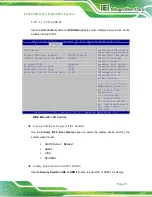
5.3.6.2
C ons ole R edirection S ettings
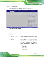
The
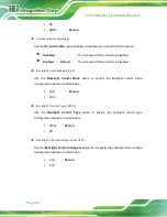
Console Redirection Settings
) allows the console redirection
options to be configured. The option is active when Console Redirection option is enabled.
Aptio Setup Utility – Copyright (C) 2017 American Megatrends, Inc.
Advanced
COM1
Console Redirection Settings
Terminal Type
[ANSI]
Bits per second
[115200]
Data Bits
[8]
Parity
[None]
Stop Bits
[1]
Emulation: ANSI:
Extended ASCII char set.
VT100: ASCII char set.
VT100+: Extends VT100 to
support color, function
keys, etc. VT-UTF8: Uses
UTF8 encoding to map
Unicode chars onto 1 or
more bytes.
---------------------
: Select Screen
↑
↓
: Select Item
Enter Select
F1 General Help
F2 Previous Values
F3
Optimized
Defaults
F4
Save
ESC Exit
Version 2.17.1255. Copyright (C) 2017 American Megatrends, Inc.
BIOS Menu 12: Console Redirection Settings
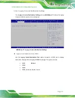
Terminal Type [ANS I]
Use the
Terminal Type
option to specify the remote terminal type.
VT100
The target terminal type is VT100
VT100+
The target terminal type is VT100+
VT-UTF8
The target terminal type is VT-UTF8
ANSI
D
EFAULT
The target terminal type is ANSI
Содержание ECN-360A-ULT3-C/4G-R10
Страница 14: ...E CN 360A ULT3 E mbedded S ys tem Page 1 Chapter 1 1 Introduction...
Страница 21: ...E CN 360A ULT3 E mbedded S ys tem Page 8 Chapter 2 2 Unpacking...
Страница 25: ...E CN 360A ULT3 E mbedded S ys tem Page 12 Chapter 3 3 Ins tallation...
Страница 32: ...E CN 360A ULT3 E mbedded S ys tem Page 19 Chapter 4 4 S ys tem Motherboard...
Страница 75: ...E CN 360A ULT3 E mbedded S ys tem Page 62 Chapter 5 5 B IOS...
Страница 115: ...E CN 360A ULT3 E mbedded S ys tem Page 102 Appendix A A R egulatory Compliance...
Страница 121: ...E CN 360A ULT3 E mbedded S ys tem Page 108 Appendix B B S afety Precautions...
Страница 126: ...E CN 360A ULT3 E mbedded S ys tem Page 113 Appendix C C Watchdog Timer...
Страница 129: ...E CN 360A ULT3 E mbedded S ys tem Page 116 Appendix D D Hazardous Materials Dis clos ure...