background image


ECN-360A-HM65  Em b e d d e d   S ys te m  

P a g e   95 

C.1


On e   Ke y  Re c o ve ry  In tro d u c tio n  

The IEI one key recovery is an easy-to-use front end for the Norton Ghost system backup 

and recovery tool. This tool provides quick and easy shortcuts for creating a backup and 

reverting to that backup or reverting to the factory default settings.   

  NOTE: 

The latest One Key Recovery software provides an auto recovery 

function that allows a system running Microsoft Windows OS to 

automatically restore from the factory default image after encountering 

a Blue Screen of Death (BSoD) or a hang for around 10 minutes. 

Please refer to Section C.3 for the detailed setup procedure.     

The IEI One Key Recovery tool menu is shown below.   


Figure C-1: IEI One Key Recovery Tool Menu 

Prior to using  the  IEI One Key Recovery  tool  (as shown i

Figure C-1

)  to backup or 

restore Windows

1.  Hardware and BIOS setup (see 

Section 

 system, five setup procedures are required.   

C.2.1

) 

2.  Create partitions (see 

Section C.2.2

) 

3.  Install operating system, drivers and system applications (see 

Section C.2.3

) 

4.  Build the recovery partition (see 

Section C.2.4

) 

5.  Create factory default image (see 

Section C.2.5

)   

Содержание ECN-360A-HM65

Страница 1: ...ys tem Page i IEI Technology Corp Us er Manual MODEL ECN 360A HM65 Embedded Sys tem with Intel Celeron dual core 847E Proces s or Dual HDMI VGA GbE Two USB 3 0 Two USB 2 0 Three COM and RoHS Compliant...

Страница 2: ...ECN 360A HM65 Embedded Sys tem Page ii Revis ion Date Version Changes 25 June 2013 1 00 Initial release...

Страница 3: ...mages arising out of the use or inability to use the product or documentation even if advised of the possibility of such damages This document contains proprietary information protected by copyright A...

Страница 4: ...ON 12 3 1 INSTALLATION PRECAUTIONS 13 3 2 INSTALLATION AND CONFIGURATION STEPS 13 3 3 HARD DISK DRIVE HDD INSTALLATION 13 3 4 WI FI ANTENNA INSTALLATION WIRELESS MODEL ONLY 15 3 5 MOUNTING BRACKET INS...

Страница 5: ...ni Card Slot 36 4 2 12 Power Connector 38 4 2 13 SATA 6Gb s Connector 39 4 2 14 SATA Power Connectors 40 4 2 15 Serial Port Connectors COM 1 and COM 2 40 4 2 16 Serial Port Connector COM3 41 4 2 17 SM...

Страница 6: ...6 Super IO Configuration 65 5 3 6 1 Serial Port n Configuration 65 5 3 7 H W Monitor 68 5 3 7 1 Smart Fan Mode Configuration 69 5 3 8 Serial Port Console Redirection 70 5 3 8 1 Console Redirection Se...

Страница 7: ...ETUP PROCEDURE FOR LINUX 115 C 5 RECOVERY TOOL FUNCTIONS 119 C 5 1 Factory Restore 120 C 5 2 Backup System 121 C 5 3 Restore Your Last Backup 122 C 5 4 Manual 123 C 6 RESTORE SYSTEMS FROM A LINUX SERV...

Страница 8: ...ECN 360A HM65 Embedded Sys tem Page viii ROHS COMPLIANT UNDER 2002 95 EC WITHOUT MERCURY 139...

Страница 9: ...ure 3 10 USB Device Connection 22 Figure 3 11 VGA Connector 23 Figure 4 1 Connectors and Jumpers Locations 25 Figure 4 2 Audio Connector Location 28 Figure 4 3 Battery Connector Location 28 Figure 4 4...

Страница 10: ...e Key Recovery Tool Menu 95 Figure C 2 Launching the Recovery Tool 100 Figure C 3 Recovery Tool Setup Menu 100 Figure C 4 Command Prompt 101 Figure C 5 Partition Creation Commands 102 Figure C 6 Launc...

Страница 11: ...8 Press any key to continue 114 Figure C 29 Partitions for Linux 116 Figure C 30 Manual Recovery Environment for Linux 117 Figure C 31 Access menu lst in Linux Text Mode 118 Figure C 32 Recovery Tool...

Страница 12: ...ts 33 Table 4 10 Backlight Inverter Connector Pinouts 34 Table 4 11 Keyboard Mouse Connector Pinouts 35 Table 4 12 LVDS Connector Pinouts 36 Table 4 13 PCIe Mini Card Slot Pinouts 38 Table 4 14 CPU Po...

Страница 13: ...Settings 50 Table 4 30 Clear CMOS Jumper Settings 51 Table 4 31 LVDS Voltage Selection Jumper Settings 52 Table 4 32 LVDS Screen Resolution Jumper Settings 53 Table 4 33 TPM Setting Jumper Settings 53...

Страница 14: ...ECN 360A HM65 Embedded Sys tem Page 1 Chapter 1 1 Introduction...

Страница 15: ...with up to 6 Gb s data transfer rate Three serial ports two USB 3 0 ports and two USB 2 0 ports ensure simplified connectivity to a variety of external peripheral devices 1 2 Model Variations The mod...

Страница 16: ...re 847E 1 1GHz Chips et Intel HM65 Sys tem Memory 2 x 204 pin DDR3 SDRAM SO DIMM System Max 8GB Pre installed DDR3 4GB memory Ethernet 2 x Realtek RTL8111E PCIe GbE controller Storage Hard Drive 1 x 2...

Страница 17: ...ility Mounting Wall mount VESA 100 Operating Temperature 10 C 55 C with air flow SSD 0 C 45 C with air flow HDD Storage Temperature 20 C 60 C Operating Shock Half sine wave shock 3G 11ms 3 shocks per...

Страница 18: ...s the following features Figure 1 3 1 x DIO connector 1 x Line out 2 x HDMI connectors 1 x 9 V 36 V power jack 1 x Reset button 2 x RJ 45 LAN connectors 2 x RS 232 DB 9 connector 1 x RS 422 485 DB 9 c...

Страница 19: ...ECN 360A HM65 Embedded Sys tem Page 6 Figure 1 3 ECN 360A HM65 Rear Panel...

Страница 20: ...ECN 360A HM65 Embedded Sys tem Page 7 1 7 Dimens ions The physical dimensions are shown below Figure 1 4 Physical Dimensions mm...

Страница 21: ...ECN 360A HM65 Embedded Sys tem Page 8 Chapter 2 2 Unpacking...

Страница 22: ...c wristband Wearing a simple anti static wristband can help to prevent ESD from damaging the board Self grounding Before handling the board touch any grounded conducting material During the time the b...

Страница 23: ...I reseller or vendor you purchased the ECN 360A HM65 from or contact an IEI sales representative directly To contact an IEI sales representative please send an email to sales iei com tw The ECN 360A H...

Страница 24: ...ECN 360A HM65 Embedded Sys tem Page 11 Quantity Item and Part Number Image 1 Utility CD 1 One Key Recovery CD Table 2 1 Package List Contents...

Страница 25: ...ECN 360A HM65 Embedded Sys tem Page 12 Chapter 3 3 Ins tallation...

Страница 26: ...and operated only by trained and qualified personnel Maintenance upgrades or repairs may only be carried out by qualified personnel who are familiar with the associated dangers Grounding The ECN 360A...

Страница 27: ...bedded Sys tem Page 14 Step 1 Remove six retention screws from the bottom panel Figure 3 1 Figure 3 1 Retention Screws Removal Step 2 Open the bottom panel and locate the HDD bracket Figure 3 2 Figure...

Страница 28: ...D Retention Screws Step 4 Replace the HDD cover and secure it using six previously removed retention screws 3 4 Wi Fi Antenna Ins tallation Wireles s Model Only To install the Wi Fi antennas to the EC...

Страница 29: ...ow the steps below Step 1 Turn the embedded system over Step 2 Align the two retention screw holes in each bracket with the corresponding retention screw holes on the sides of the bottom surface Step...

Страница 30: ...eral interface connectors Audio devices HDMI devices RJ 45 Ethernet cable Serial devices USB devices VGA monitor To install these devices connect the corresponding cable connector from the actual devi...

Страница 31: ...ector Step 3 Check audio clarity Check that the sound is coming through the right speakers by adjusting the balance front to rear and left to right 3 6 2 HDMI Device Connection The HDMI connector tran...

Страница 32: ...ector is being inserted with the right way up 3 6 3 LAN Connection There are two external RJ 45 LAN connectors The RJ 45 connector enables connection to an external network To connect a LAN cable with...

Страница 33: ...are two RS 232 DB 9 connectors and one RS 422 485 DB 9 connector of the ECN 360A HM65 for serial device connection Follow the steps below to connect a serial device to the DB 9 connector of the ECN 36...

Страница 34: ...the USB 3 0 driver before connecting a USB device to the system or else the system may not recognize the connected device There are four USB 3 0 connectors and two USB 2 0 connectors on the ECN 360A H...

Страница 35: ...CRT or VGA monitor To connect a monitor to the ECN 360A HM65 please follow the instructions below Step 1 Locate the female DB 15 connector The location of the female DB 15 connector is shown in Chapt...

Страница 36: ...d Sys tem Page 23 Figure 3 11 VGA Connector Step 4 Secure the connector Secure the DB 15 VGA connector from the VGA monitor to the external interface by tightening the two retention screws on either s...

Страница 37: ...ECN 360A HM65 Embedded Sys tem Page 24 Chapter 4 4 Sys tem Motherboard...

Страница 38: ...nectors The ECN 360A HM651 embedded system motherboard comes with a number of peripheral interface connectors and configuration jumpers 4 1 1 Layout Figure 4 1 shows the on board peripheral interface...

Страница 39: ...T1 Fan connector CPU 4 pin wafer CPU_FAN1 Fan connector system 3 pin wafer SYS_FAN1 Front panel connector 10 pin header F_PANEL1 Inverter connector 5 pin wafer INVERTER1 Keyboard and mouse connector 6...

Страница 40: ...SB_CON2 USB 3 0 ports USB port USB_CON3 VGA port connector 15 pin female VGA1 Table 4 2 Rear Panel Connectors 4 2 Internal Peripheral Connectors This section has complete descriptions of all the inter...

Страница 41: ...7 GND 8 GND 9 LMIC1 CONN R 10 LMIC1 CONN L Table 4 3 Audio Connector Pinouts 4 2 2 Battery Connector CN Label BAT1 CN Type 2 pin wafer 1x2 CN Location See Figure 4 3 CN Pinouts See Table 4 4 This is...

Страница 42: ...eader 2x5 CN Location See Figure 4 4 CN Pinouts See Table 4 5 The digital input output connector is managed through a Super I O chip The DIO connector pins are user programmable Figure 4 4 DIO Connect...

Страница 43: ...ation See Figure 4 5 CN Pinouts See Table 4 6 The debug connector connects to a debug card for debugging Figure 4 5 EC Debug Connector Location Pin Description 1 V5S 2 V3 3S 3 GND 4 INT_SERIRQ 5 LPC_A...

Страница 44: ...ing fan The connector has a rotation pin to get rotation signals from fans and notify the system so the system BIOS can recognize the fan speed Please note that only specified fans can issue the rotat...

Страница 45: ...ed Please note that only specified fans can issue the rotation signals Figure 4 7 System Fan Connector Location Pin Description 1 Rotation Signal 2 12V 3 GND Table 4 8 System Fan Connector Pinouts 4 2...

Страница 46: ...6 PWR_LED Power Button 2 PWR_BTN 7 PWR_LED 3 PWR_BTN 8 PWR_LED HDD LED 4 HDD_LED Reset 9 RESET 5 HDD_LED 10 RESET Table 4 9 Front Panel Connector Pinouts 4 2 8 LVDS Backlight Inverter Connector CN Lab...

Страница 47: ...OUND 5 BACKLIGHT ENABLE Table 4 10 Backlight Inverter Connector Pinouts 4 2 9 Keyboard Mous e Connector CN Label KB_MS1 CN Type 6 pin wafer 1x6 CN Location See Figure 4 10 CN Pinouts See Table 4 11 Th...

Страница 48: ...ription 1 VCC5_KBMS 2 MS DATA 3 MS CLK 4 KB DATA 5 KB CLK 6 GROUND Table 4 11 Keyboard Mouse Connector Pinouts 4 2 10 LVDS LCD Connector CN Label LVDS1 CN Type 30 pin crimp 2x15 CN Location See Figure...

Страница 49: ...6 A_Y1 7 A_Y2 8 A_Y2 9 A_CK 10 A_CK 11 A_Y3 12 A_Y3 13 GND 14 GND 15 B_Y0 16 B_Y0 17 B_Y1 18 B_Y1 19 B_Y2 20 B_Y2 21 B_CK 22 B_CK 23 B_Y3 24 B_Y3 25 GND 26 GND 27 VCC VCC3 28 VCC VCC3 29 VCC VCC3 30...

Страница 50: ...rs wireless LAN WLAN cards and mSATA cards Figure 4 12 PCIe Mini Card Slot Location Pin Description Pin Description 1 PCIE_WAKE 2 VCC3 3 N C 4 GND 5 N C 6 1 5V 7 N C 8 N C 9 GND 10 N C 11 CLK 12 N C 1...

Страница 51: ...44 N C 45 N C 46 N C 47 N C 48 1 5V 49 N C 50 GND 51 N C 52 VCC3 Table 4 13 PCIe Mini Card Slot Pinouts 4 2 12 Power Connector CN Label PWR1 CN Type 4 pin connector 2x2 CN Location See Figure 4 13 CN...

Страница 52: ...or CN Label S_ATA1 S_ATA2 CN Type 7 pin SATA drive connector CN Location See Figure 4 14 CN Pinouts See Table 4 15 The SATA connectors connect to SATA hard drives or optical drives with data transfer...

Страница 53: ...is 2A CN1 CN2 Figure 4 15 SATA Power Connector Locations Pin Description 1 V5S 2 GND Table 4 16 SATA Power Connector Pinouts 4 2 15 RS 232 Serial Port Connectors COM 1 and COM 2 CN Label COM1 COM2 CN...

Страница 54: ...ption 1 NDCD 6 NCTS 2 NDSR 7 NDTR 3 NSIN 8 XRI 4 NRTS 9 GND 5 NSOUT 10 GND Table 4 17 COM Connector Pinouts 4 2 16 RS 422 485 Serial Port Connector COM3 CN Label COM3 CN Type 4 pin wafer 1x4 CN Locati...

Страница 55: ...TXD485 Table 4 18 Serial Port Connector Pinouts Use the optional RS 422 485 cable to connect to a serial device The pinouts of the DB 9 connector are listed below RS 422 Pinouts RS 485 Pinouts Table 4...

Страница 56: ...nt Bus device Figure 4 18 SMBus Connector Location Pin Description 1 GND 2 SMB_DATA 3 SMB_CLK 4 V5S Table 4 20 SMBus Connector Pinouts 4 2 18 SPI Flas h Connector CN Label J SPI1 CN Type 6 pin wafer 1...

Страница 57: ...LK_SW 8 GND Table 4 21 SPI Flash Connector 4 3 External Peripheral Interface Connector Panel Figure 4 20 shows the motherboard external peripheral interface connector EPIC panel The EPIC panel consist...

Страница 58: ...iption Pin Description 1 LAN1_MDI0 7 LAN1_MDI2 2 LAN1_MDI0 8 LAN1_MDI2 3 LAN1_MDI1 9 LAN1_MDI3 4 LAN1_MDI1 10 LAN1_MDI3 Table 4 22 LAN Pinouts Figure 4 21 RJ 45 Ethernet Connector The RJ 45 Ethernet c...

Страница 59: ...ice with HDMI interface Pin Description Pin Description 1 HDMI_DATA2 13 N C 2 GND 14 N C 3 HDMI_DATA2 15 HDMI_SCL 4 HDMI_DATA1 16 HDMI_SDA 5 GND 17 GND 6 HDMI_DATA1 18 5V 7 HDMI_DATA0 19 HDMI_HPD 8 GN...

Страница 60: ...s Pin Description 1 VCC 2 DATA 3 DATA 4 GND Table 4 25 USB 2 0 Port Pinouts 4 3 4 USB 3 0 Connectors CN Label USB_CON3 CN Type USB 3 0 port CN Location See Figure 4 20 CN Pinouts See Table 4 26 The US...

Страница 61: ...ts See Figure 4 23 and Table 4 27 The motherboard has a single 15 pin female connector for connectivity to standard display devices Figure 4 23 VGA Connector Pin Description Pin Description 1 RED 2 GR...

Страница 62: ...from a jumper The jumpers on the motherboard are listed in Table 4 28 Des cription Label Type AT ATX power mode select J_ATXCTL1 3 pin header Clear CMOS J_CMOS1 3 pin header LVDS voltage select J_VLVD...

Страница 63: ...Figure 4 25 If the ECN 360A HM65 fails to boot due to improper BIOS settings the clear CMOS jumper clears the CMOS data and resets the system BIOS information To do this use the jumper cap to close p...

Страница 64: ...r Settings The location of the clear CMOS jumper is shown in Figure 4 25 below Figure 4 25 Clear CMOS Jumper 4 4 3 LVDS Voltage Selection J umper Warning Incorrect voltages can destroy the LCD panel M...

Страница 65: ...8 pin header J umper Settings See Table 4 32 J umper Location See Figure 4 27 The LVDS Panel Resolution Selection jumper allows the LVDS screen voltage to be set The LVDS Panel Resolution Selection ju...

Страница 66: ...8bit Short all LVDS Disabled Table 4 32 LVDS Screen Resolution Jumper Settings Figure 4 27 LVDS Screen Resolution Jumper Locations 4 4 5 TPM Setting J umper J umper Label ME_RTC1 J umper Type 3 pin he...

Страница 67: ...header J umper Settings See Table 4 34 J umper Location See Figure 4 29 The Flash Descriptor Security Override jumper specifies whether to override the flash descriptor Setting Description Short 1 2...

Страница 68: ...ECN 360A HM65 Embedded Sys tem Page 55 Chapter 5 5 BIOS...

Страница 69: ...el to enter SETUP message appears on the screen 0 If the message disappears before the DELETE or F2 key is pressed restart the computer and try again 5 1 2 Us ing Setup Use the arrow keys to highlight...

Страница 70: ...4 Unable to Reboot After Configuration Changes If the computer cannot boot after changes to the system configuration is made CMOS defaults Use the jumper described in Chapter 4 5 1 5 BIOS Menu Bar Th...

Страница 71: ...Tab to switch between Data elements Select Screen Select Item EnterSelect Change Opt F1 General Help F2 Previous Values F3 Optimized Defaults F4 Save Exit ESC Exit Version 2 10 1208 Copyright C 2010...

Страница 72: ...o Setup Utility Copyright C 2010 American Megatrends Inc Main Advanced Chipset Boot Security Save Exit ACPI Settings RTC Wake Settings CPU Configuration SATA Configuration USB Configuration F81866 Sup...

Страница 73: ...Megatrends Inc BIOS Menu 3 ACPI Configuration ACPI Sleep State S1 CPU Stop Clock Use the ACPI Sleep State option to specify the sleep state the system enters when it is not being used Suspend Disabled...

Страница 74: ...atrends Inc BIOS Menu 4 RTC Wake Settings Wake s ys tem with Fixed Time Dis abled Use the Wake system with Fixed Time option to enable or disable the system wake on alarm event Disabled DEFAULT The re...

Страница 75: ...Select Item EnterSelect Change Opt F1 General Help F2 Previous Values F3 Optimized Defaults F4 Save Exit ESC Exit Version 2 10 1208 Copyright C 2010 American Megatrends Inc BIOS Menu 5 CPU Configurat...

Страница 76: ...ion menu BIOS Menu 6 to change and or set the configuration of the SATA devices installed in the system Aptio Setup Utility Copyright C 2010 American Megatrends Inc Advanced SATA Configuration SATA Mo...

Страница 77: ...it Version 2 10 1208 Copyright C 2010 American Megatrends Inc BIOS Menu 7 USB Configuration USB Devices The USB Devices Enabled field lists the USB devices that are enabled on the system Legacy USB Su...

Страница 78: ...Help F2 Previous Values F3 Optimized Defaults F4 Save Exit ESC Exit Version 2 10 1208 Copyright C 2010 American Megatrends Inc BIOS Menu 8 Super IO Configuration 5 3 6 1 Serial Port n Configuration Us...

Страница 79: ...ted IO 3F8h IRQ 4 Serial Port I O port address is 3F8h and the interrupt address is IRQ4 IO 3F8h IRQ 3 4 Serial Port I O port address is 3F8h and the interrupt address is IRQ3 4 IO 2F8h IRQ 3 4 Serial...

Страница 80: ...ort I O port address is 2F8h and the interrupt address is IRQ3 4 IO 3E8h IRQ 3 4 Serial Port I O port address is 3E8h and the interrupt address is IRQ3 4 IO 2E8h IRQ 3 4 Serial Port I O port address i...

Страница 81: ...is 2E0h and the interrupt address is IRQ10 5 3 7 H W Monitor The H W Monitor menu BIOS Menu 10 contains the fan configuration submenus and displays operating temperature fan speeds and system voltage...

Страница 82: ...temperature and speed settings Aptio Setup Utility Copyright C 2010 American Megatrends Inc Advanced Smart Fan Mode Configuration CPU Fan Smart Fan Control Auto Duty Cycle Mode Temperature 1 60 Tempe...

Страница 83: ...l Auto Duty Cycle Mode Use the SYS Fan Smart Fan Control option to configure the CPU Smart Fan Manual Duty Mode The fan spins at the speed set in Manual by Duty Cycle settings Auto Duty Cycle Mode DEF...

Страница 84: ...F2 Previous Values F3 Optimized Defaults F4 Save Exit ESC Exit Version 2 10 1208 Copyright C 2010 American Megatrends Inc BIOS Menu 12 Serial Port Console Redirection Cons ole Redirection Dis abled U...

Страница 85: ...General Help F2 Previous Values F3 Optimized Defaults F4 Save ESC Exit Version 2 10 1208 Copyright C 2010 American Megatrends Inc BIOS Menu 13 Console Redirection Settings Terminal Type ANSI Use the T...

Страница 86: ...No parity bit is sent with the data bits Even The parity bit is 0 if the number of ones in the data bits is even Odd The parity bit is 0 if the number of ones in the data bits is odd Mark The parity b...

Страница 87: ...ng this function Select Screen Select Item EnterSelect Change Opt F1 General Help F2 Previous Values F3 Optimized Defaults F4 Save Exit ESC Exit Version 2 10 1208 Copyright C 2010 American Megatrends...

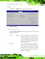
Страница 88: ...tility Copyright C 2010 American Megatrends Inc Main Advanced Chipset Boot Security Save Exit NorthBridge Configuration SouthBridge Configuration North Bridge Parameters Select Screen Select Item Ente...

Страница 89: ...Auto Graphics Configuration Check to enable VT d function on MCH Select Screen Select Item EnterSelect Change Opt F1 General Help F2 Previous Values F3 Optimized Defaults F4 Save Exit ESC Exit Version...

Страница 90: ...r Setting 1024x768 24BIT Backlight Control Normal Select DVMT 5 0 Pre Allocated Fixed Graphics Memory size used by the Internal Graphics Device Select Screen Select Item EnterSelect Change Opt F1 Gene...

Страница 91: ...to select the display device used by the system when it boots Configuration options are listed below AUTO DEFAULT CRT LVDS HDMI1 HDMI2 LCD Panel Type By Hardware Use the LCD Panel Type option to sele...

Страница 92: ...Bridge Configuration Auto Power Button Status Disable ATX Restore AC Power Loss Last State Azalia Enabled Azalia Internal HDMI codec Enabled Select AC power state when power is re applied after a powe...

Страница 93: ...dio controller Disabled The onboard High Definition Audio controller is disabled Enabled DEFAULT The onboard High Definition Audio controller is detected automatically and enabled Azalia internal HDMI...

Страница 94: ...Version 2 10 1208 Copyright C 2010 American Megatrends Inc BIOS Menu 19 Boot Bootup NumLock State On Use the Bootup NumLock State BIOS option to specify if the number lock setting must be modified dur...

Страница 95: ...r disable boot option for legacy network devices Disabled DEFAULT Ignore all PXE Option ROMs Enabled Load PXE Option ROMs Option ROM Mes s ages Keep Current Use the Option ROM Messages option to set t...

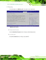
Страница 96: ...his is a power on password and must be entered to boot or enter Setup In Setup the User will have Administrator rights The password must be 3 to 20 characters long Administrator Password User Password...

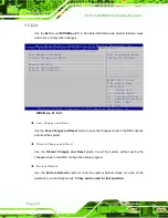
Страница 97: ...t Item EnterSelect Change Opt F1 General Help F2 Previous Values F3 Optimized Defaults F4 Save Exit ESC Exit Version 2 10 1208 Copyright C 2010 American Megatrends Inc BIOS Menu 21 Exit Save Changes a...

Страница 98: ...Page 85 Save as Us er Defaults Use the Save as User Defaults option to save the changes done so far as user defaults Res tore Us er Defaults Use the Restore User Defaults option to restore the user de...

Страница 99: ...ECN 360A HM65 Embedded Sys tem Page 86 A Safety Precautions Appendix A...

Страница 100: ...never the ECN 360A HM65 is being installed moved or modified Do not apply voltage levels that exceed the specified voltage range Doing so may cause fire and or an electrical shock Electric shocks can...

Страница 101: ...d the following anti static precautions are strictly adhered to Wear an anti static wristband Wearing a simple anti static wristband can help to prevent ESD from damaging any electrical component Self...

Страница 102: ...rical and electronic products carrying the mark left must be disposed of separately from normal household waste This includes monitors and electrical accessories such as signal cables or power cords W...

Страница 103: ...ll be explicitly mentioned in the cleaning tips Below is a list of items to use when cleaning the ECN 360A HM65 Cloth Although paper towels or tissues can be used a soft clean piece of cloth is recomm...

Страница 104: ...ECN 360A HM65 Embedded Sys tem Page 91 B BIOS Menu Options Appendix B...

Страница 105: ...d 66 Change Settings Auto 67 Serial Port Enabled 67 Change Settings Auto 67 PC Health Status 69 CPU Fan Smart Fan Control Auto Duty Cycle Mode 70 Temperature n 70 SYS Fan Smart Fan Control Auto Duty C...

Страница 106: ...dec Enabled 80 Bootup NumLock State On 81 Quiet Boot Enabled 82 Launch PXE OpROM Disabled 82 Option ROM Messages Keep Current 82 UEFI Boot Disabled 82 Administrator Password 83 User Password 83 Save C...

Страница 107: ...ECN 360A HM65 Embedded Sys tem Page 94 Appendix C C One Key Recovery...

Страница 108: ...store from the factory default image after encountering a Blue Screen of Death BSoD or a hang for around 10 minutes Please refer to Section C 3 for the detailed setup procedure The IEI One Key Recover...

Страница 109: ...be used with IEI products The software will fail to run and a warning message will appear when used on non IEI hardware To create the system backup the main storage device must be split into two parti...

Страница 110: ...if the operating system is already installed C 1 2 Supported Operating Sys tem The recovery CD is compatible with both Microsoft Windows and Linux operating systems OS The supported OS versions are li...

Страница 111: ...OS setup see Section C 2 1 Step 2 Create partitions see Section C 2 2 Step 3 Install operating system drivers and system applications see Section C 2 3 Step 4 Build the recovery partition see Section...

Страница 112: ...rity 1 st Boot Device Step 7 Save changes and restart the computer Continue to the next section for instructions on partitioning the internal storage S t e p 0 C 2 2 Create Partitions To create the sy...

Страница 113: ...ECN 360A HM65 Embedded Sys tem Page 100 Figure C 2 Launching the Recovery Tool Step 3 The recovery tool setup menu is shown as below Figure C 3 Recovery Tool Setup Menu Step 4 Press 6 then Enter...

Страница 114: ...the other is for saving recovery files and images which will be an invisible partition Press Enter after entering each line below system32 diskpart DISKPART list vol DISKPART sel disk 0 DISKPART crea...

Страница 115: ...ECN 360A HM65 Embedded Sys tem Page 102 Figure C 5 Partition Creation Commands...

Страница 116: ...ng system onto the unlabelled partition The partition labeled Recovery is for use by the system recovery tool and should not be used for installing the operating system or any applications NOTE The op...

Страница 117: ...the system Step 3 Boot the system from the recovery CD When prompted press any key to boot from the recovery CD It will take a while to launch the recovery tool Please be patient Figure C 6 Launching...

Страница 118: ...process the partition created for recovery files in Section C 2 2 is hidden and the recovery tool is saved in this partition Figure C 8 Building the Recovery Partition Step 6 After completing the sys...

Страница 119: ...ollow the steps below Step 1 Turn on the system When the following screen displays Figure C 10 press the F3 key to access the recovery tool The message will display for 10 seconds please press F3 befo...

Страница 120: ...Page 107 Figure C 12 About Symantec Ghost Window Step 4 Use mouse to navigate to the option shown below Figure C 13 Figure C 13 Symantec Ghost Path Step 5 Select the local source drive Drive 1 as show...

Страница 121: ...own in Figure C 15 Then click OK Figure C 15 Select a Source Partition from Basic Drive Step 7 Select 1 2 Recovery NTFS drive and enter a file name called iei Figure C 16 Click Save The factory defaul...

Страница 122: ...360A HM65 Embedded Sys tem Page 109 Figure C 16 File Name to Copy Image to Step 8 When the Compress Image screen in Figure C 17 prompts click High to make the image file smaller Figure C 17 Compress I...

Страница 123: ...C 18 Image Creation Confirmation Step 10 The Symantec Ghost starts to create the factory default image Figure C 19 Figure C 19 Image Creation Complete Step 11 When the image creation completes a scre...

Страница 124: ...the following sections CAUTION The setup procedure may include a step to create a factory default image It is suggested to configure the system to a factory default environment before the configurati...

Страница 125: ...om the recovery CD When prompted press any key to boot from the recovery CD It will take a while to launch the recovery tool Please be patient Figure C 23 Launching the Recovery Tool Step 4 When the r...

Страница 126: ...very tool is saved in this partition Figure C 25 Building the Auto Recovery Partition Step 6 After completing the system configuration the following message prompts to confirm whether to create a fact...

Страница 127: ...completing the system configuration press any key in the following window to restart the system Figure C 28 Press any key to continue Step 9 Eject the One Key Recovery CD and restart the system Step...

Страница 128: ...SC Exit Version 2 11 1210 Copyright C 2011 American Megatrends Inc BIOS Menu 22 iEi Feature Step 12 Save changes and restart the system If the system encounters a Blue Screen of Death BSoD or a hang f...

Страница 129: ...RUB v0 97 or earlier and Ext3 the Symantec Ghost may not function properly While installing Linux OS please create two partitions Partition 1 Partition 2 SWAP NOTE Please reserve enough space for part...

Страница 130: ...recovery tool setup menu appears type 3 and press Enter Figure C 30 The Symantec Ghost window appears and starts configuring the system to build a recovery partition After completing the system confi...

Страница 131: ...Linux Text Mode Step 6 Modify the menu lst as shown below Step 7 The recovery tool menu appears Figure C 32 Figure C 32 Recovery Tool Menu Step 8 Create a factory default image Follow Step 2 Step 12...

Страница 132: ...the F3 key The recovery tool main menu is shown below Figure C 33 Recovery Tool Main Menu The recovery tool has several functions including 1 Factory Restore Restore the factory default image iei GHO...

Страница 133: ...ry Res tore To restore the factory default image please follow the steps below Step 1 Type 1 and press Enter in the main menu Step 2 The Symantec Ghost window appears and starts to restore the factory...

Страница 134: ...Step 1 Type 2 and press Enter in the main menu Step 2 The Symantec Ghost window appears and starts to backup the system A backup image called iei_user GHO is created in the hidden Recovery partition...

Страница 135: ...t system backup please follow the steps below Step 1 Type 3 and press Enter in the main menu Step 2 The Symantec Ghost window appears and starts to restore the last backup image iei_user GHO Figure C...

Страница 136: ...st system backup please follow the steps below Step 1 Type 4 and press Enter in the main menu Step 2 The Symantec Ghost window appears Use the Ghost program to backup or recover the system manually Fi...

Страница 137: ...orted client OS includes Windows 2000 Windows 7 Windows XP Windows CE Windows Vista Windows XP Embedded Prior to restoring client systems from a Linux server a few setup procedures are required Step 1...

Страница 138: ...em default settings dhcpd conf CentOS Use the following command to show the DHCP server sample location vi etc dhcpd conf The DHCP server sample location is shown as below Use the following command to...

Страница 139: ...x CentOS apt get install tftpd hpa xinetd syslinux Debian Step 2 Enable the TFTP server by editing the etc xinetd d tftp file and make it use the remap file The vvv is optional but it could definitely...

Страница 140: ...as shown below vi etc xinetd d tftp C 6 3 Configure One Key Recovery Server Settings Step 1 Copy the Utility RECOVERYR10 TAR BZ2 package from the One Key Recovery CD to the system server side Step 2 E...

Страница 141: ...reload Debian etc init d xinetd restart etc init d dhcp3 server restart C 6 5 Create Shared Directory Step 1 Install the samba yum install samba Step 2 Create a shared directory for the factory defaul...

Страница 142: ...Step 4 Edit etc samba smb conf for your environment For example Step 5 Modify the hostname vi etc hostname Modify RecoveryServer C 6 6 Setup a Client Sys tem for Auto Recovery Step 1 Configure the fo...

Страница 143: ...the auto recovery utility into the system by double clicking the Utility AUTORECOVERY SETUP exe in the One Key Recovery CD This utility MUST be installed in the system otherwise the system will automa...

Страница 144: ...5 Embedded Sys tem Page 131 NOTE A firewall or a SELinux is not in use in the whole setup process If there is a firewall or a SELinux protecting the system modify the configuration information to acco...

Страница 145: ...g one key recovery Please follow the steps below to install the SATA RAID AHCI driver Step 1 Copy the SATA RAID AHCI driver to a floppy disk and insert the floppy disk into a USB floppy disk drive The...

Страница 146: ...age 133 Step 5 When the following window appears press S to select Specify Additional Device Step 6 In the following window select a SATA controller mode used in the system Then press Enter The user c...

Страница 147: ...tep 4 in Section C 2 2 Create Partitions to finish the whole setup process S t e p 0 C 7 2 Sys tem Memory Requirement To be able to access the recovery tool by pressing F3 while booting up the system...

Страница 148: ...ECN 360A HM65 Embedded Sys tem Page 135 D Watchdog Timer Appendix D...

Страница 149: ...A BIOS function call INT 15H is used to control the Watchdog Timer INT 15H AH 6FH Sub function AL 2 Sets the Watchdog Timer s period BL Time out value Its unit second is dependent on the item Watchdo...

Страница 150: ...the system resets Example program INITIAL TIMER PERIOD COUNTER W_LOOP MOV AX 6F02H setting the time out value MOV BL 05 time out value is 5 seconds INT 15H ADD THE APPLICATION PROGRAM HERE CMP EXIT_A...

Страница 151: ...ECN 360A HM65 Embedded Sys tem Page 138 Appendix E E Hazardous Materials Dis clos ure...

Страница 152: ...s the presences of small quantities of certain materials in the product and is applicable to China RoHS only A label will be placed on each product to indicate the estimated Environmentally Friendly U...

Страница 153: ...uit Board X O O O O X Metal Fas teners X O O O O O Cable As s embly X O O O O X Fan As s embly X O O O O X Power Supply As s emblies X O O O O X Battery O O O O O O O This toxic or hazardous substance...
Страница 154: ...N 360A HM65 Embedded Sys tem Page 141 RoHS RoHS Pb Hg Cd CR VI PBB PBDE X O O O O X X O O O O X X O O O O X X O O O O O X O O O O X X O O O O X X O O O O X O O O O O O O SJ T11363 2006 X SJ T11363 200...

Отзывы: