IEI Technology DRPC-124-EHL Series Скачать руководство пользователя страница 21


DRPC-124-EHL 

Page  9 

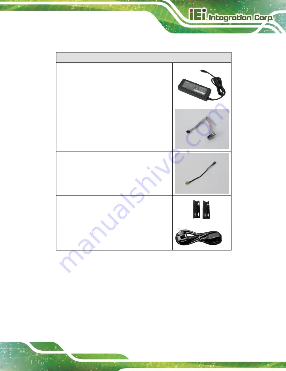
The following table lists the optional items that can be purchased separately. 

Optional 

Power Adapter 

(

P/N

: 63040-430084-000-RS) 


Serial cable 

(

P/N

: 32205-008000-100-RS) 


DC Power Cord   

(

P/N

: 32102-045700-100-RS) 


Wall mounting kit 

(

P/N

: 41020-0522C2-00-HF*2) 


AC Power Cord   

(

P/N

: 32702-000202-100-RS) 


Содержание DRPC-124-EHL Series

Страница 1: ...NAME User Manual Fanless embedded system with Intel Celeron J6412 2 0GHz up to 2 6 GHz Quad Core TDP 10W on board 8GB LPDDR4x memory 4 x USB 1 x HDMI 4 x GbE LAN 12 28V DC RoHS MODEL DRPC 124 EHL Ser...

Страница 2: ...DRPC 124 EHL Page II MODEL NAME Revision Date Version Changes July 28 2023 1 00 Initial release...

Страница 3: ...s arising out of the use or inability to use the product or documentation even if advised of the possibility of such damages This document contains proprietary information protected by copyright All r...

Страница 4: ...ON Cautionary messages should be heeded to help reduce the chance of losing data or damaging the product NOTE These messages inform the reader of essential but non critical information These messages...

Страница 5: ...LATION PRECAUTIONS 11 3 2 BACK COVER REMOVAL 12 3 3 STORAGE INSTALLATION 13 3 4 IO EXTENSION INSTALLATION OPTIONAL 13 3 5 BACK COVER INSTALLATION 15 3 6 MOUNTING THE SYSTEM 15 3 6 1 DIN Rail Installat...

Страница 6: ...CONNECTOR 36 4 13 FLASH EC ROM CONNECTOR 37 4 14 I2 C CONNECTOR 38 4 15 HDMI DEBUG CONNECTOR 39 4 16 INTERNAL USB 2 0 CONNECTORS 40 4 17 DIGITAL INPUT OUTPUT CONNECTOR 40 4 18 FRONT PANEL CONNECTOR 4...

Страница 7: ...ion Settings 67 5 3 6 NVMe Configuration 70 5 4 CHIPSET 70 5 4 1 System Agent SA Configuration 71 5 4 1 1 Memory Configuration 73 5 4 1 2 Graphics Configuration 74 5 4 2 PCH IO Configuration 76 5 4 2...

Страница 8: ...onnection 18 Figure 3 11 RJ 45 Ethernet Connector 19 Figure 3 12 Power Connector 20 Figure 3 13 USB Connection 20 Figure 3 14 Power Input 21 Figure 4 1 Connector and Jumper Locations 25 Figure 4 2 Cle...

Страница 9: ...1 Figure 4 16 Front panel Connector Location 42 Figure 4 17 M 2 B key Slot Location 43 Figure 4 18 M 2 B key Slot Location 45 Figure 4 19 M 2 M key Slot Location 47 Figure 5 1 BIOS Starting Menu 50 Fi...

Страница 10: ...e Setting Jumper Pinouts 30 Table 4 6 Battery Connector Pinouts 32 Table 4 7 Buzzer Connector Pinouts 33 Table 4 8 RS 232 422 485 Serial Port Connector Pinouts 34 Table 4 9 SATA 6Gb s Drive Connectors...

Страница 11: ...5571 H W Monitor 66 BIOS Menu 12 Serial Port Console Redirection 67 BIOS Menu 13 COM Console Redirection Settings 68 BIOS Menu 14 NVMe configuration 70 BIOS Menu 15 Chipset 71 BIOS Menu 16 System Agen...

Страница 12: ......

Страница 13: ...DRPC 124 EHL Page 1 Chapter 1 1 Introduction...

Страница 14: ...with onboard 8GB LPDDR4x memory up to 16GB and including one HDMI four GbE LAN ports four USB ports one RS 232 422 485 optional 1 2 Features The DRPC 124 EHL Series features are listed below Intel Ce...

Страница 15: ...GbE by I210 controller 3 x RJ 45 PCIe 2 5 GbE by I225V controller Display 1 x HDMI 1 4b up to 4k 30Hz COM 1x RS 232 422 485 DB9 Optional TPM2 0 Intel PTT Other 1 x Power Button with LED 1 x Clear BIO...

Страница 16: ...UKCA Watchdog timer Programmable 1 255 sec min OS Supported OS Microsoft Windows 10 11 Linux Table 1 1 Technical Specifications 1 4 Front Panel The front panel of the DRPC 124 EHL Series has the foll...

Страница 17: ...DRPC 124 EHL Page 5 1 5 Physical Dimensions The physical dimensions of the DRPC 124 EHL Series are shown in Figure 1 3 Figure 1 3 Physical Dimensions...

Страница 18: ...DRPC 124 EHL Page 6 Chapter 2 2 Unpacking...

Страница 19: ...earing a simple anti static wristband can help to prevent ESD from damaging the board Self grounding Before handling the board touch any grounded conducting material During the time the board is handl...

Страница 20: ...e IEI reseller or vendor you purchased the DRPC 124 EHL Series from or contact an IEI sales representative directly To contact an IEI sales representative please send an email to sales ieiworld com Th...

Страница 21: ...optional items that can be purchased separately Optional Power Adapter P N 63040 430084 000 RS Serial cable P N 32205 008000 100 RS DC Power Cord P N 32102 045700 100 RS Wall mounting kit P N 41020 05...

Страница 22: ...DRPC 124 EHL Page 10 Chapter 3 3 Installation...

Страница 23: ...is opened while the power cord is still connected to an electrical outlet Qualified Personnel The DRPC 124 EHL Series must be installed and operated only by trained and qualified personnel Maintenanc...

Страница 24: ...lling or maintaining the internal components the back cover must be removed from the DRPC 124 EHL Follow the steps below to complete the task Step 1 Loosen the 7 screws on the top cover Step 2 Take of...

Страница 25: ...the notch on the module with the notch on the slot Slide the M 2 module into the socket at an angle of about 20 Figure 3 2 Figure 3 2 Inserting the M 2 Module into the Slot at an Angle Step 4 Secure t...

Страница 26: ...tep 2 Connect the serial cable to the serial connector on the mainboard Figure 3 4 Figure 3 4 RS 232 Cable Installation Step 3 Knock out the reserved holes on the chassis and Secure the DB9 end of the...

Страница 27: ...n the 7 screws on the side Figure 3 6 Figure 3 6 Back Cover Installation 3 6 Mounting The System DRPC 124 EHL comes with standard rail mounting bracket and optional wall mounting bracket Follow these...

Страница 28: ...cket with the corresponding retention screw holes on the rear surface Step 3 Secure the brackets to the system by inserting retention screws Figure 3 7 Figure 3 7 DIN Rail Mounting Bracket Installatio...

Страница 29: ...s into each bracket Figure 3 8 Figure 3 8 Mounting Bracket Retention Screw 3 7 External Peripheral Interface Connectors The DRPC 124 EHL Series has the following connectors Detailed descriptions of th...

Страница 30: ...nectors Align the RJ 45 connector on the LAN cable with one of the RJ 45 connectors on the DRPC 124 EHL Series See Figure 3 10 LAN Connection Step 3 Insert the LAN cable RJ 45 connector Once aligned g...

Страница 31: ...tivity Link LED Speed LED STATUS DESCRIPTION STATUS DESCRIPTION Off No link Off 10 Mbps connection Yellow Linked Orange 1000 Mbps connection Blinking TX RX activity Green 2 5 Gbps connection Table 3 2...

Страница 32: ...the instructions below Step 1 Located the USB connectors The locations of the USB connectors are shown in Chapter 1 Step 2 Align the connectors Align the USB device connector with one of the connector...

Страница 33: ...rnal electronic components and may also cause injury to the user The power of the system needs more than 12 28V 60W Step 1 Connect the power source to the power input terminal Step 2 Push the power bu...

Страница 34: ...er to find all the relevant software utilities and documentation IEI Resource Download Center 3 9 1 Driver Download To download drivers from IEI Resource Download Center follow the steps below Step 1...

Страница 35: ...ollowing window You can download the entire ISO file or click the small arrow to find an individual driver and click the file name to download NOTE To install software from the downloaded ISO image fi...

Страница 36: ...DRPC 124 EHL Page 24 Chapter 4 4 System Motherboard...

Страница 37: ...ctors and jumpers of the system motherboard are listed in the following sections 4 2 Layout The following diagram shows the locations of the internal external connectors and jumpers on the motherboard...

Страница 38: ...in header J_DNX1 Flash SPI ROM connector 6 pin wafer JBIOS1 I2C connector 4 pin wafer I2C1 Flash EC ROM connector 8 pin header EC_SPI1 Buzzer Connector 2 pin wafer BZ1 Battery connector 2 pin wafer BA...

Страница 39: ...ple if you have forgotten the password you should clear the CMOS and then reset the password you should disconnect the RTC battery and press the button for about 3 seconds This will set back to normal...

Страница 40: ...Figure 4 3 CN Pinouts See Table 4 3 The AT ATX power mode selection is made through the AT ATX power mode switch which is shown in Figure 4 3 Figure 4 3 AT ATX Power Mode Switch Locations PIN NO DESCR...

Страница 41: ...pe 2 pin header P 1 27mm CN Location See Figure 4 4 CN Pinouts See Table 4 4 The J_DNX1 connector is used for set DNX mode Figure 4 4 DNX Mode Setting Jumper Location Table 4 4 DNX Mode setting Jumper...

Страница 42: ...00mm CN Location See Figure 4 5 CN Pinouts See Table 4 5 The J_FLASH1 connector is used for Flash Descriptor Security Overide Figure 4 5 Flash Descriptor Override Setting Jumper Locations PIN NO DESCR...

Страница 43: ...the ME firmware update 4 8 RTC Battery Connector CAUTION Risk of explosion if battery is replaced by an incorrect type Only certified engineers should replace the on board battery Dispose of used batt...

Страница 44: ...n 1 VBATT 2 GND Table 4 6 Battery Connector Pinouts 4 9 Buzzer Connector CN Label BZ1 CN Type 2 pin wafer p 1 25 mm CN Location See Figure 4 7 CN Pinouts See Table 4 7 The buzzer connector is connecte...

Страница 45: ...DRPC 124 EHL Page 33 Figure 4 7 Buzzer Connector Location Pin Description 1 5V 2 PC_BEEP Table 4 7 Buzzer Connector Pinouts...

Страница 46: ...m CN Location See Figure 4 8 CN Pinouts See Table 4 8 The serial connector provides RS 232 422 485 connection Figure 4 8 RS 232 422 485 Serial Port Connector Location PIN NO DESCRIPTION PIN NO DESCRIP...

Страница 47: ...nouts See Table 4 9 The SATA 6Gb s drive connector is connected to a SATA 6Gb s drive The SATA 6Gb s drive transfers data at speeds as high as 6Gb s Figure 4 9 Mini SATA Connectors Location PIN NO DES...

Страница 48: ...Connectors Pinouts 4 12 Flash SPI ROM Connector CN Label JBIOS1 CN Type 6 pin wafer p 1 25 mm CN Location See Figure 4 10 CN Pinouts See Table 4 10 The 6 pin Flash SPI ROM connector is used to flash...

Страница 49: ...lash SPI ROM Connector Pinouts 4 13 Flash EC ROM Connector CN Label EC_SPI1 CN Type 8 pin header p 1 27 mm CN Location See Figure 4 11 CN Pinouts See Table 4 11 The 8 pin Flash EC ROM connector is use...

Страница 50: ...K 7 GND 8 SPI_SI Table 4 11 Flash EC ROM Connector Pinouts 4 14 I2 C Connector CN Label I2C1 CN Type 4 pin wafer p 1 25 mm CN Location See Figure 4 12 CN Pinouts See Table 4 12 The SMBus System Manage...

Страница 51: ...I C Connector Pinouts 4 15 HDMI Debug Connector CN Label J1 CN Type 3 pin header p 2 00 mm CN Location See Figure 4 13 CN Pinouts See Table 4 13 Figure 4 13 HDMI Debug Connector Location Pin Descript...

Страница 52: ...des two USB 2 0 ports by dual port USB cable Figure 4 14 Internal USB 2 0 Connectors Locations PIN NO DESCRIPTION PIN NO DESCRIPTION 1 VCC 2 GND 3 USB DATA 4 USB DATA 5 USB DATA 6 USB DATA 7 GND 8 VCC...

Страница 53: ...devices Figure 4 15 Digital I O Connector Location PIN NO DESCRIPTION PIN NO DESCRIPTION 1 GND 2 VCC 3 DOUT5 4 DOUT4 5 DOUT3 6 DOUT2 7 DOUT1 8 DOUT0 9 DIN5 10 DIN4 11 DIN3 12 DIN2 13 DIN1 14 DIN0 Tabl...

Страница 54: ...front panel connector connects to the indicator LEDs reset button on the system front panel Figure 4 16 Front panel Connector Location PIN NO DESCRIPTION PIN NO DESCRIPTION 1 GND 2 PWRBTN_N 3 GND 4 PM...

Страница 55: ...key 2242 slot with PCIe Gen3 x2 signals Figure 4 17 M 2 B key Slot Location Pin Description Pin Description 1 GND 2 V3 3_B1 3 GND 4 V3 3_B1 5 GND 6 NC 7 NC 8 V3 3_B1 9 NC 10 M2M_LED_N 11 GND 12 NC 13...

Страница 56: ...38 NC 39 GND 40 M 2_SMCLK 41 PCIE_RXN6 42 M 2_SMDAT 43 PCIE_RXP6 44 NC 45 GND 46 NC 47 PCIE_TXN6 48 NC 49 PCIE_TXP6 50 PLT_RST_N 51 GND 52 NC 53 CLK_M2_B_N 54 NC 55 CLK_M2_B_P 56 NC 57 GND 58 NC 59 NC...

Страница 57: ...e M 2 B key 2242 slot with SATA signal Figure 4 18 M 2 B key Slot Location Pin Description Pin Description 1 GND 2 V3 3_B2 3 GND 4 V3 3_B2 5 GND 6 NC 7 NC 8 NC 9 NC 10 V3 3_B2 11 GND 12 NC 13 Module K...

Страница 58: ...X0 44 NC 45 GND 46 NC 47 SATA_RX0 48 NC 49 SATA_RX0 50 PLT_RST_N 51 GND 52 NC 53 NC 54 NC 55 NC 56 NC 57 GND 58 NC 59 NC 60 NC 61 NC 62 NC 63 NC 64 NC 65 NC 66 NC 67 NC 68 NC 69 GND 70 V3 3_B2 71 GND...

Страница 59: ...ON PIN NO DESCRIPTION 1 GND 2 V3P3S_SSD 3 GND 4 V3P3S_SSD 5 NC 6 NC 7 NC 8 NC 9 GND 10 M2M_LED_N 11 NC 12 V3P3S_SSD 13 NC 14 V3P3S_SSD 15 GND 16 V3P3S_SSD 17 NC 18 V3P3S_SSD 19 NC 20 NC 21 GND 22 NC 2...

Страница 60: ...E_TXP4 50 PLT_RST_N 51 GND 52 PLT_RST_N 53 CLK_M2_M_N 54 TP320 55 CLK_M2_M_P 56 N C 57 GND 58 N C 59 Module Key 60 Module Key 61 Module Key 62 Module Key 63 Module Key 64 Module Key 65 Module Key 66 M...

Страница 61: ...DRPC 124 EHL Page 49 Chapter 5 5 BIOS...

Страница 62: ...e 5 1 1 Starting Setup The UEFI BIOS is activated when the computer is turned on The setup program can be activated in one of two ways 1 Using keyboard Press the DEL or F2 as soon as the system is tur...

Страница 63: ...on the right hand side Increase the numeric value or make changes Decrease the numeric value or make changes Page Up Move to the previous page Page Dn Move to the next page Esc Main Menu Quit and not...

Страница 64: ...Button Function Previous Values Load the last value you set Optimized Defaults Load the factory default values in order to achieve the best performance Back Return to the previous menu Soft kbd Displa...

Страница 65: ...efaults Use the clear CMOS button described in Chapter 4 5 1 5 BIOS Menu Bar The menu bar on top of the BIOS screen has the following main items Main Changes the basic system configuration Advanced Ch...

Страница 66: ...tup program is entered The Main menu gives an overview of the basic system information BIOS Menu 1 Main 1 2 BIOS Menu 2 Main 2 2 BIOS Information The BIOS Information lists a brief summary of the BIOS...

Страница 67: ...r Speed ID Displays the Processor ID Stepping Displays the Processor Stepping Package Displays the Processor Package Number of Processors Displays number of CPU cores Microcode Revision CPU Microcode...

Страница 68: ...m Overview field also has two user configurable fields System Date xx xx xx Use the System Date option to set the system date Manually enter the day month and year System Time xx xx xx Use the System...

Страница 69: ...Menu 3 to configure the CPU and peripheral devices through the following sub menus BIOS Menu 3 Advanced WARNING Setting the wrong values in the sections below may cause the system to malfunction Make...

Страница 70: ...Configuration Use the CPU Configuration menu BIOS Menu 4 BIOS Menu 5 BIOS Menu 6 to view detailed CPU specifications or enable the Intel Virtualization Technology BIOS Menu 4 CPU Configuration 1 3 BIO...

Страница 71: ...ranges to be supported Disabled Disables more than two frequency ranges Enabled DEFAULT Enables more than two frequency ranges C states Disabled Use the C states option to enable or disable the CPU Po...

Страница 72: ...cores in the processor package Power Limit 1 Use the Power Limit 1 to set Power Limit in Milli Watts BIOS will round to the nearest 1 8W when programming 0 no custom override For 12 50W enter 12500 O...

Страница 73: ...Enabled Use the Turbo Mode option to enable or disable Turbo Mode which requires Intel Speed Step or Intel Speed Shift to be available and enabled Disabled Disables Turbo Mode Technology Enabled DEFAU...

Страница 74: ...d Computing Security Device Support Enable Use the Security Device Support option to configure support for the Security Device Disable Security Device support is disabled Enable DEFAULT Security Devic...

Страница 75: ...ration menu BIOS Menu 8 to set or change the configurations for the serial ports BIOS Menu 8 IT5571 Super IO Configuration 5 3 3 1 Serial Port 1 Configuration Use the Serial Port 1 Configuration menu...

Страница 76: ...DEFAULT Enable the serial port Device Settings The Device Settings option shows the serial port IO port address and interrupt address IO 3F8h IRQ 4 Serial Port I O port address is 3F8h and the interru...

Страница 77: ...rt 2 Configuration Menu Serial Port Enabled Use the Serial Port option to enable or disable the serial port Disabled Disable the serial port Enabled DEFAULT Enable the serial port Device Settings The...

Страница 78: ...system parameters and values are shown The system parameters that are monitored are o CPU Temperature o System Temperature o V3P3DSW o V3P3S o V5S 5 3 5 Serial Port Console Redirection The Serial Port...

Страница 79: ...Disabled the console redirection function Enabled Enabled the console redirection function The Console Redirection Settings submenu will be available when the Console Redirection option is enabled 5...

Страница 80: ...pe is VT UTF8 ANSI DEFAULT The target terminal type is ANSI Bits per second 115200 Use the Bits per second option to specify the serial port transmission speed The speed must match on the other side L...

Страница 81: ...with the data bits Even The parity bit is 0 if the number of ones in the data bits is even Odd The parity bit is 0 if the number of ones in the data bits is odd Mark The parity bit is always 1 This op...

Страница 82: ...display the NVMe controller BIOS Menu 14 NVMe configuration 5 4 Chipset Use the Chipset menu BIOS Menu 15 to access the PCH IO and System Agent SA configuration menus WARNING Setting the wrong values...

Страница 83: ...System Agent SA Configuration Use the System Agent SA Configuration menu BIOS Menu 16 to configure the System Agent SA parameters BIOS Menu 16 System Agent SA Configuration VT d Enabled Use the VT d...

Страница 84: ...DRPC 124 EHL Page 72 Disabled Disable the VT d capability Enabled DEFAULT Enable the VT d capability...

Страница 85: ...DRPC 124 EHL Page 73 5 4 1 1 Memory Configuration Use the Memory Configuration submenu BIOS Menu 17 to view memory information BIOS Menu 17 Memory Configuration...

Страница 86: ...8 menu to configure the video device connected to the system BIOS Menu 18 Graphics Configuration Primary Display Auto Use the Primary Display option to select the primary graphics controller the syste...

Страница 87: ...GFX DVMT Pre Allocated 160M Use the DVMT Pre Allocated option to set the amount of system memory allocated to the integrated graphics processor when the system boots The system memory allocated can th...

Страница 88: ...EHL Page 76 5 4 2 PCH IO Configuration Use the PCH IO Configuration menu BIOS Menu 19 BIOS Menu 20 to configure the PCH parameters BIOS Menu 19 PCH IO Configuration 1 2 BIOS Menu 20 PCH IO Configurat...

Страница 89: ...ystem remains turned off Power On The system turns on Last State DEFAULT The system returns to its previous state If it was on it turns itself on If it was off it remains off Power Saving Function EUP...

Страница 90: ...USB Power SW3 5V DUAL Use the USB Power SW3 BIOS option to configure the USB power source for the corresponding USB connectors Figure 5 4 5V DUAL DEFAULT Sets the USB power source to 5V dual 5V Sets...

Страница 91: ...DRPC 124 EHL Page 79 5 4 2 1 PCI Express Configuration Use the PCI Express Configuration submenu BIOS Menu 21 to configure the PCI Express slots BIOS Menu 21 PCI Express Configuration...

Страница 92: ...the PCI Root Port Setting BIOS Menu 22 PCIe Slot Configuration Submenu PCIe Speed Auto Use the PCIe Speed option to specify the PCI Express port speed Configuration options are listed below Auto DEFA...

Страница 93: ...o configure whether to detect if a non compliance PCI Express device is connected to the PCI Express port Disabled DEFAULT Do not detect if a non compliance PCI Express device is connected to the PCI...

Страница 94: ...SATA Configuration SATA Mode Selection AHCI Use the SATA Mode Selection option to determine how the SATA devices operate AHCI DEFAULT Configures SATA devices as AHCI device Hot Plug Disabled Use the...

Страница 95: ...onfigure the PCH Azalia settings BIOS Menu 24 HD Audio Configuration HD Audio Enabled Use the HD Audio option to enable or disable the High Definition Audio controller Disabled The onboard High Defini...

Страница 96: ...curity menu BIOS Menu 25 to set system and user passwords BIOS Menu 25 Security Administrator Password Use the Administrator Password to set or change a administrator password User Password Use the Us...

Страница 97: ...Quiet Boot BIOS option to select the screen display when the system boots Disabled Normal POST messages displayed Enabled DEFAULT OEM Logo displayed instead of POST messages Launch PXE OpROM Disabled...

Страница 98: ...pherals you selected The following Boot Options are listed as an example Boot Option 1 Sets the system boot order ADATA SP580 as the first priority Windows Boot Manager P1 ADATA SSD SP580 240GB Disabl...

Страница 99: ...he BIOS options and reset the system Discard Changes and Reset Use the Discard Changes and Reset option to exit the system without saving the changes made to the BIOS configuration setup program Resto...

Страница 100: ...DRPC 124 EHL Page 88 Restore User Defaults Use the Restore User Defaults option to restore the user defaults to all the setup options...

Страница 101: ...DRPC 124 EHL Page 89 Appendix A A Regulatory Compliance...

Страница 102: ...ce that may cause undesired operation This equipment has been tested and found to comply with the limits for a Class A digital device pursuant to part 15 of the FCC Rules These limits are designed to...

Страница 103: ...DRPC 124 EHL Page 91 Appendix B B Product Disposal...

Страница 104: ...d as electronic device in terms of the European Directive 2012 19 EU WEEE and must not be disposed of as domestic garbage EU wide legislation as implemented in each Member State requires that waste el...

Страница 105: ...DRPC 124 EHL Page 93 Appendix C C Error Beep Code...

Страница 106: ...und 4 Recovery failed 4 S3 Resume failed 7 Reset PPI is not available C 2 DXE Beep Codes Number of Beeps Description 1 Invalid password 4 Some of the Architectural Protocols are not available 5 No Con...

Страница 107: ...DRPC 124 EHL Page 95 Appendix D D Hazardous Materials Disclosure...

Страница 108: ...ybromina ted Diphenyl Ethers PBDE Bis 2 ethylh exyl phthalate DEHP Butyl benzyl phthalate BBP Dibutyl phthalate DBP Diisobutyl phthalate DIBP Housing O O O O O O O O O O Printed Circuit Board O O O O...

Страница 109: ...EHL Page 97 D 2 China RoHS RoHS RoHS Pb Hg Cd CR VI PBB PBDE O O O O O O O O O O O O O O O O O O O O O O O O O O O O O O O O O O O O O O O O O O O SJ T11364 2014 GB T26572 2011 X SJ T11364 2014 GB T26...

Отзывы: