


AFL2-W21A/AB-H61 P a n e l P C
P a g e 173
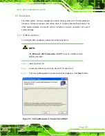
8.9
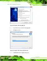
Wi-Fi Drive r In s ta lla tio n
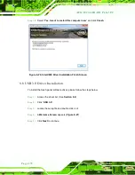
To install the wireless LAN driver, please follow the steps below.
S te p 1:
Access the driver list. (See
Section 8.2
S te p 2:
Click “
WiFi
” and select the folder which corresponds to your operating system.
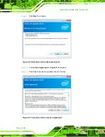
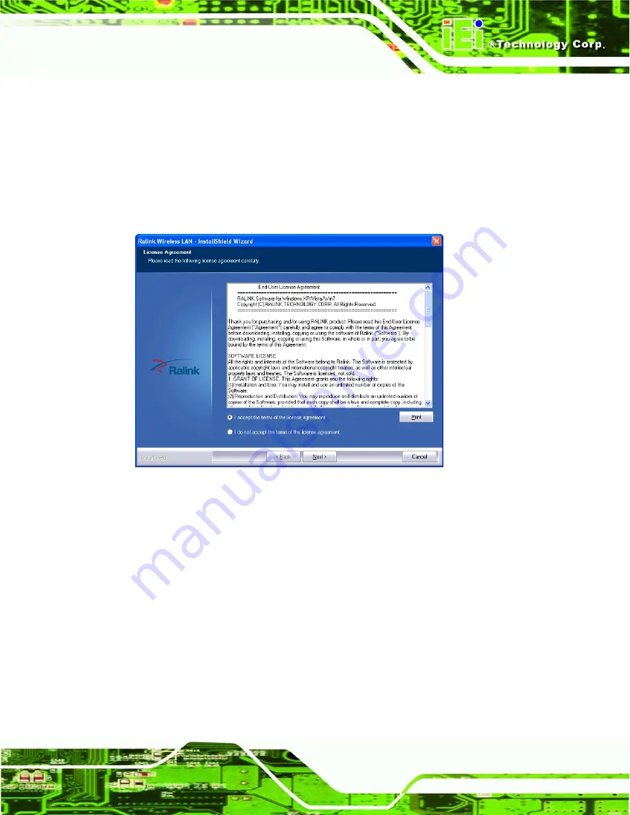
S te p 3:
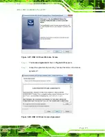
The
License Agreement
Figure 8-31: License Agreement
S te p 4:
Accept the conditions of the license agreement and click
NEXT
to continue.
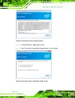
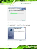
S te p 5:
The
Setup Type
screen in
Содержание AFL2-W21A/AB-H61 SERIES
Страница 2: ...AFL2 W21A AB H61 Page II Revis ion Date Version Changes 16 April 2013 1 00 Initial release...
Страница 20: ...AFL2 W21A AB H61 Page 1 1 Introduction Chapter 1...
Страница 32: ...AFL2 W21A AB H61 Page 13 2 LED Light Bar Optional Chapter 2...
Страница 54: ...AFL2 W21A AB H61 Page 35 3 Unpacking Chapter 3...
Страница 58: ...AFL2 W21A AB H61 Page 39 4 Ins tallation Chapter 4...
Страница 88: ...AFL2 W21A AB H61 Page 69 5 Sys tem Motherboard Chapter 5...
Страница 124: ...AFL2 W21A AB H61 Page 105 Figure 5 36 LCD panel Selection Jumper Location...
Страница 125: ...AFL2 W21A AB H61 Page 106 6 Sys tem Maintenance Chapter 6...
Страница 134: ...AFL2 W21A AB H61 Page 115 7 BIOS Setup Chapter 7...
Страница 171: ...AFL2 W21A AB H61 Page 152 8 Software Drivers Chapter 8...
Страница 201: ...AFL2 W21A AB H61 Panel PC Page 182 9 Cooling Management Cons ole iCMC Chapter 9...
Страница 210: ...AFL2 W21A AB H61 Panel PC Page 191 A Safety Precautions Appendix A...
Страница 215: ...AFL2 W21A AB H61 Panel PC Page 196 B BIOS Menu Options Appendix B...
Страница 218: ...AFL2 W21A AB H61 Panel PC Page 199 Appendix C C One Key Recovery...
Страница 226: ...AFL2 W21A AB H61 Panel PC Page 207 Figure C 5 Partition Creation Commands...
Страница 259: ...AFL2 W21A AB H61 Panel PC Page 240 D Hazardous Materials Dis clos ure Appendix D...