background image


AFL-W10A-N270 User Manual 

Page 115


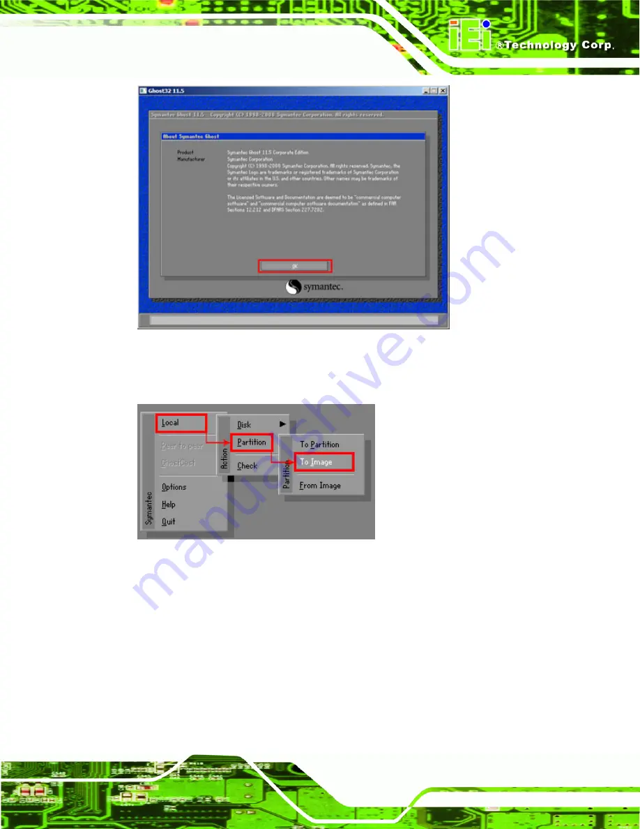
Figure B-12: About Symantec Ghost Window 

Step 4: 

Use mouse to navigate to the option shown below (

Figure B-13

).  


Figure B-13: Symantec Ghost Path 

Step 5: 

Select the local source drive (Drive 1) as shown in 

Figure B-14

. Then click OK.   

Содержание AFL-W10A-N270

Страница 1: ...Technology Corp User Manual MODEL AFL W10A N270 Panel PC with Touch Screen and Intel Atom N270 1 6GHz CPU Gigabit Ethernet Wireless LAN USB 2 0 External SATA RS 232 422 485 Audio RoHS Compliant IP 64...

Страница 2: ...umper Location 20 December 2011 2 12 Minor update to Table 2 8 COM3 RX Function Select Jumper Settings 4 October 2011 2 11 Added Section 2 5 4 1 COM3 RS 422 and RS 485 Pinouts Added Appendix B One Key...

Страница 3: ...es arising out of the use or inability to use the product or documentation even if advised of the possibility of such damages This document contains proprietary information protected by copyright All...

Страница 4: ...1 Packing List 24 2 2 REMOVING THE REAR PANEL 27 2 3 CF CARD INSTALLATION 28 2 4 AT ATX MODE SELECTION 30 2 4 1 AT Power Mode 31 2 4 2 ATX Power Mode 31 2 5 JUMPER SETTINGS 32 2 5 1 Access the Jumpers...

Страница 5: ...54 3 4 MEMORY MODULE REPLACEMENT 56 3 5 CF CARD REPLACEMENT 57 3 6 REINSTALLING THE COVERS 57 4 BIOS OPTIONS 58 4 1 INTRODUCTION 59 4 1 1 Starting Setup 59 4 1 2 Using Setup 59 4 1 3 Getting Help 60 4...

Страница 6: ...UTIONS 100 A 2 1 Maintenance and Cleaning 100 A 2 2 Cleaning Tools 101 B ONE KEY RECOVERY 102 B 1 ONE KEY RECOVERY INTRODUCTION 103 B 1 1 System Requirement 104 B 1 2 Supported Operating System 105 B...

Страница 7: ...e DHCP TFTP and HTTP 137 B 6 5 Create Shared Directory 137 B 6 6 Setup a Client System for Auto Recovery 138 B 7 OTHER INFORMATION 141 B 7 1 Using AHCI Mode or ALi M5283 VIA VT6421A Controller 141 B 7...

Страница 8: ...on 37 Figure 2 8 COM3 TX Function Select Jumper Pinout Locations 38 Figure 2 9 COM3 RS 232 422 485 Serial Port Select Jumper Location 39 Figure 2 10 Wall mounting Bracket 40 Figure 2 11 Chassis Suppor...

Страница 9: ...Figure B 14 Select a Local Source Drive 116 Figure B 15 Select a Source Partition from Basic Drive 116 Figure B 16 File Name to Copy Image to 117 Figure B 17 Compress Image 117 Figure B 18 Image Creat...

Страница 10: ...y Default 129 Figure B 36 Recovery Complete Window 129 Figure B 37 Backup System 130 Figure B 38 System Backup Complete Window 130 Figure B 39 Restore Backup 131 Figure B 40 Restore System Backup Comp...

Страница 11: ...Settings 34 Table 2 4 COM1 Pin 9 Setting Jumper Settings 35 Table 2 5 COM3 Pin 9 Setting Jumper Settings 35 Table 2 6 RS 422 Pinouts 36 Table 2 7 RS 485 Pinouts 36 Table 2 8 COM3 RX Function Select J...

Страница 12: ...n 73 BIOS Menu 8 Power Configuration 76 BIOS Menu 9 ACPI Configuration 77 BIOS Menu 10 APM Configuration 78 BIOS Menu 11 Remote Access Configuration 80 BIOS Menu 12 USB Configuration 83 BIOS Menu 13 P...

Страница 13: ...AFL W10A N270 User Manual Page 13 Chapter 1 1 Introduction...

Страница 14: ...tput controller hub ensures optimal memory graphics and peripheral I O support The system comes with 1 0 GB of preinstalled DDR2 SDRAM and supports a maximum of 2 0 GB of DDR2 SDRAM ensuring smooth da...

Страница 15: ...es of a screen rear panel top panel bottom panel and two side panels left and right An ABS PC plastic front frame surrounds the front screen The rear panel provides screw holes for a wall mounting bra...

Страница 16: ...16 Figure 1 2 AFL W10A N270 Front View 1 2 2 Rear Panel The rear panel provides access to the internal components of the AFL W10A N270 and CF card slot Refer to Figure 1 3 for back cover retention sc...

Страница 17: ...W10A N270 has the following I O interface connectors 1 x 12 V DC IN connector 1 x Audio line out jack 1 x external SATA port 1 x MIC in jack 1 x Power switch 1 x Reset button 2 x RJ 45 LAN connectors...

Страница 18: ...l Overview The AFL W10A N270 has the following components installed internally 1 x Motherboard 1 x 1 0 GB 533 MHz DDR2 SDRAM SO DIMM 1 x Wireless module 2 x 1 5W speaker Figure 1 5 Internal Overview 1...

Страница 19: ...SO DIMM 2GB Max I O Ports and Switches One 12V DC power jack One Audio line out jack One External SATA port One MIC in jack One Power switch One Reset switch Two RJ 45 for Giga LAN One RS 232 serial...

Страница 20: ...tion Temperature C 10 C 50 C Storage Temperature C 20 C 60 C Net Weight 1 4 Kg IP Level Front Frame IP64 EMC CE FCC CCC Safety CB Touch Screen Resistive 5 Wire Power Adapter 40W Power Adapter 100VAC 2...

Страница 21: ...AFL W10A N270 User Manual Page 21 Figure 1 6 AFL W10A N270 Dimensions mm...

Страница 22: ...AFL W10A N270 User Manual Page 22 Chapter 2 2 Installation...

Страница 23: ...eople should install the panel PC Take anti static precautions Electrostatic discharge can destroy electrical components and injure the user Users must ground themselves using an anti static wristband...

Страница 24: ...ly cut deep enough to break the tape Step 2 Open the outside box Step 3 Carefully cut the tape sealing the box Only cut deep enough to break the tape Step 4 Open the inside box Step 5 Lift the monitor...

Страница 25: ...02 RS 1 Screw kit 4 x M3 5mm P N 44013 030041 RS 1 User manual CD and driver CD 1 One Key Recovery CD 1 Touch pen P N XTR104 0002 RS Optional WIN CE 6 0 ALFCF W10 N270 CE060 WIN XPE ALFCF W10 N270 XPE...

Страница 26: ...FL W10A N270 User Manual Page 26 Wall mounting kit P N AFLWK 19 Rack mounting kit P N AFLRK 10 VSTAND P N VSTAND A12 Stand P N STAND A12 Stand P N STAND 100 RS Stand P N STAND 150 RS Arm P N ARM 11 RS...

Страница 27: ...S B10 R10 DC 9 36V Input UPS AUPS B20 R10 Make sure all the components listed in the packing list are present If any of these items are missing or damaged contact the distributor or sales representati...

Страница 28: ...move it More strength is required to separate the cover from the chassis Step 0 2 3 CF Card Installation The AFL W10A N270 has one CF Type II slot inside the rear panel The slot can be access without...

Страница 29: ...270 User Manual Page 29 Figure 2 2 CF card slot location Step 2 Insert a CF card into the slot Figure 2 3 Figure 2 3 CF Card Location Step 3 Replace the CF card slot cover Step 4 Reinsert retention sc...

Страница 30: ...N270 The selection is made through an AT ATX switch on the top edge of the inner aluminum cover Figure 2 4 To select AT mode or ATX mode follow the steps below Step 1 Locate the AT ATX switch on the...

Страница 31: ...ATM Self service kiosk Plant environment monitoring system Factory automation platform Manufacturing shop flow 2 4 2 ATX Power Mode With the ATX mode selected the AFL W10A N270 panel PC goes in a sta...

Страница 32: ...an be found on the motherboard installed in the AFL W10A N270 Before the panel PC is installed the jumpers must be set in accordance with the desired configuration The jumpers on the AFL W10A N270 mot...

Страница 33: ...der Table 2 2 Preconfigured Jumpers 2 5 3 Clear CMOS Jumper Jumper Label J_CMOS1 Jumper Type 2 pin header Jumper Settings See Table 2 3 Jumper Location See Figure 2 5 If the AFL W10A N270 fails to boo...

Страница 34: ...efault Short 2 3 Clear CMOS Setup Table 2 3 Clear CMOS Jumper Settings The location of the clear CMOS jumper is shown in Figure 2 5 below Figure 2 5 Clear CMOS Jumper 2 5 4 COM Port Pin 9 Select Jumpe...

Страница 35: ...n use 5 V Short 7 9 COM1 RI Pin use RI Default Table 2 4 COM1 Pin 9 Setting Jumper Settings JP10 Description Short 1 2 COM3 RI Pin use 12 V Short 3 4 COM3 RI Pin use RI Default Short 5 6 COM3 RI Pin u...

Страница 36: ...nouts 2 5 5 COM3 RX Function Select Jumper Jumper Label JP9 Jumper Type 8 pin header Jumper Settings See Table 2 8 Jumper Location See Figure 2 7 The COM3 RX Function Select jumper sets the communicat...

Страница 37: ...he COM3 TX Function Select jumper configures the TX pin on COM3 serial port connector as RS 422 as an RS 485 The COM3 TX Function Select jumper selection options are shown in Table 2 9 COM3 TX Functio...

Страница 38: ...Figure 2 9 The COM3 RS 232 422 485 Serial Port Select jumper sets the communication protocol used by the second serial communications port COM3 as RS 232 RS 422 or RS 485 The COM3 RS 232 422 485 Seri...

Страница 39: ...232 422 485 Serial Port Select Jumper Location 2 6 Mounting the System WARNING When mounting the panel PC onto an arm onto the wall or onto a panel it is better to have more than one person to help wi...

Страница 40: ...the bracket retention screws Step 4 Align the wall mounting bracket screw holes with the pilot holes Step 5 Secure the mounting bracket to the wall by inserting the retention screws into the four pilo...

Страница 41: ...securely in the slotted holes Figure 2 11 Ensure that all four of the mounting screws fit snuggly into their respective slotted holes NOTE In the diagram below the bracket is already installed on the...

Страница 42: ...1 Select the position on the panel to mount the panel PC Step 2 Cut out a section from the panel that corresponds to the rear panel dimensions of the panel PC Take care that the panel section that is...

Страница 43: ...luminum frame is flush against the panel Step 4 Insert the panel mounting clamps into the pre formed holes along the edges of the chassis behind the aluminum frame Step 5 Tighten the screws that pass...

Страница 44: ...r to the panel mounting installation To do this please follow the steps below NOTE When purchasing the cabinet rack installation bracket make sure it is compatible with both the AFL W10A N270 panel PC...

Страница 45: ...he panel PC behind the ABS PC plastic frame Step 3 Tighten the screws that pass through the rack mounting clamps until the plastic caps at the front of all the screws are firmly secured to the bracket...

Страница 46: ...Video Electronics Standards Association compliant and can be mounted on an arm with a 100mm interface pad To mount the panel PC on an arm please follow the steps below Step 1 Please correctly mount th...

Страница 47: ...ew Holes Step 4 Secure the panel PC to the interface pad by inserting the retention screws through the bottom of the mounting arm interface pad and into the panel PC Step 0 2 7 Bottom Panel Connectors...

Страница 48: ...r into the onboard RJ 45 connector Step 0 2 7 2 Serial Device Connection The AFL W10A N270 has two DB 9 connectors for connecting to RS 232 and RS 232 422 485 serial devices on the bottom panel Follow...

Страница 49: ...tor Step 0 2 7 3 USB Device Connection There are four external USB 2 0 connectors All connectors are perpendicular to the AFL W10A N270 To connect a USB 2 0 or USB 1 1 device please follow the instruc...

Страница 50: ...the onboard connector Step 0 2 8 Power Connection The power cable connects the power adapter to the power outlet The power adapter and power cable are required for operation of the panel PC Step 1 Con...

Страница 51: ...t technical support for the latest updates The following drivers can be installed on the system each driver is in its own directory on the driver CD Chipset driver Graphics driver LAN driver Audio dri...

Страница 52: ...AFL W10A N270 User Manual Page 52 Chapter 3 3 System Maintenance...

Страница 53: ...n working on the internal components Some internal components are easily damaged or destroyed by electrostatic discharge Take antistatic precautions to prevent electrostatic discharge Step 1 If the co...

Страница 54: ...motherboard is accessible after opening the rear cover 3 3 Cover Removal To access the AFL W10A N270 internally the back panel must be removed To remove the back panel please follow the steps below St...

Страница 55: ...e cover and pull down the cover a bit to make it possible to fully remove it More strength is required to separate the cover from the chassis Step 5 Remove the retention screws Figure 3 3 from the alu...

Страница 56: ...ocket Location Step 3 Remove the DDR memory module by pulling both the spring retainer clips outward from the socket Step 4 Grasp the DDR memory module by the edges and carefully pull it out of the so...

Страница 57: ...tion A 1 2 Step 2 Turn off the power See Section 3 1 Step 3 Follow the instruction listed in Section 2 3 to replace the CF card Step 0 3 6 Reinstalling the Covers WARNING Failing to reinstall the cove...

Страница 58: ...AFL W10A N270 User Manual Page 58 Chapter 4 4 BIOS Options...

Страница 59: ...ssage appears on the screen 0 If the message disappears before the DELETE key is pressed restart the computer and try again 4 1 2 Using Setup Use the arrow keys to highlight items press ENTER to selec...

Страница 60: ...ot After Configuration Changes If the computer cannot boot after changes to the system configuration is made CMOS defaults Use the jumper described in Chapter 5 4 1 5 BIOS Menu Bar The menu bar on top...

Страница 61: ...ct Screen Select Item Enter Go to SubScreen F1 General Help F10 Save and Exit ESC Exit v02 61 Copyright 1985 2006 American Megatrends Inc BIOS Menu 1 Main System Overview The System Overview lists a b...

Страница 62: ...Advanced menu 5BIOS Menu 2 to configure the CPU and peripheral devices through the following sub menus WARNING Setting the wrong values in the sections below may cause the system to malfunction Make...

Страница 63: ...Inc BIOS Menu 2 Advanced 4 3 1 CPU Configuration Use the CPU Configuration menu 5BIOS Menu 3 to view detailed CPU specifications and configure the CPU BIOS SETUP UTILITY Main Advanced PCIPNP Boot Sec...

Страница 64: ...Primary IDE Master Not Detected Primary IDE Slave Not Detected Secondary IDE Master Not Detected Secondary IDE Slave Not Detected Disabled Compatible Enhanced Select Screen Select Item Enter Go to Su...

Страница 65: ...p BIOS automatically detects the presence of IDE devices The BIOS displays the status of the auto detected IDE devices The following IDE devices are detected and are shown in the IDE Configuration men...

Страница 66: ...parameters are listed as follows Device Lists the device type e g hard disk CD ROM etc Type Indicates the type of devices a user can manually select Vendor Lists the device manufacturer Size List the...

Страница 67: ...channel CD DVD The CD DVD option specifies that an IDE CD ROM drive is attached to the specified IDE channel The BIOS does not attempt to search for other types of IDE disk drives on the specified cha...

Страница 68: ...mode program timing cycles between the IDE drive and the programmable IDE controller As the PIO mode increases the cycle time decreases Auto DEFAULT BIOS auto detects the PIO mode Use this value if th...

Страница 69: ...MWDMA2 Multi Word DMA mode 2 selected with a maximum data transfer rate of 16 6MBps UDMA1 Ultra DMA mode 0 selected with a maximum data transfer rate of 16 6MBps UDMA1 Ultra DMA mode 1 selected with...

Страница 70: ...from using 32 bit data transfers Enabled DEFAULT Allows BIOS to use 32 bit data transfers on supported hard disk drives 4 3 3 Super I O Configuration Use the Super I O Configuration menu 5BIOS Menu 6...

Страница 71: ...IRQ3 Serial Port 1 I O port address is 2E8 and the interrupt address is IRQ3 Serial Port1 Mode Normal Use the Serial Port1 Mode option to select the transmitting and receiving mode for the first seria...

Страница 72: ...IRQ option to select the interrupt address for serial port 4 Disabled No base address is assigned to serial port 3 2E8 DEFAULT Serial port 4 I O port address is 2E8 Serial Port4 IRQ 10 Use the Serial...

Страница 73: ...m Enter Go to SubScreen F1 General Help F10 Save and Exit ESC Exit v02 61 Copyright 1985 2006 American Megatrends Inc BIOS Menu 7 Hardware Health Configuration CPU FAN Mode Setting Full On Mode Use th...

Страница 74: ...value select the CPU Temp Limit of OFF option and enter a decimal number between 000 and 127 The temperature range is specified below Minimum Value 0 C Maximum Value 127 C CPU Temp Limit of Start 020...

Страница 75: ...To select a value select the Fan 3 Start PWM option and enter a decimal number between 000 and 127 The temperature range is specified below PWM Minimum Mode 0 PWM Maximum Mode 127 Slope PWM 0 5 PWM T...

Страница 76: ...r Configuration The Power Configuration menu BIOS Menu 8 configures the Advanced Configuration and Power Interface ACPI and Power Management APM options BIOS SETUP UTILITY Main Advanced PCIPNP Boot Se...

Страница 77: ...Save and Exit ESC Exit v02 61 Copyright 1985 2006 American Megatrends Inc BIOS Menu 9 ACPI Configuration Suspend Mode S1 POS Use the Suspend Mode BIOS option to specify the sleep state the system ent...

Страница 78: ...yright 1985 2006 American Megatrends Inc BIOS Menu 10 APM Configuration Restore on AC Power Loss Last State Use the Restore on AC Power Loss BIOS option to specify what state the system returns to if...

Страница 79: ...Enabled Wake event generated by activity on the keyboard or mouse Resume on Ring Disabled Use the Resume on Ring BIOS option to enable activity on the RI ring in modem line to rouse the system from a...

Страница 80: ...te Access Configuration menu BIOS Menu 11 to configure remote access parameters The Remote Access Configuration is an AMIBIOS feature and allows a remote host running a terminal program to display and...

Страница 81: ...Type These configuration options are discussed below Serial Port Number COM1 Use the Serial Port Number option to select the serial port used for remote access COM1 DEFAULT System is remotely accessed...

Страница 82: ...nal software and the slave Redirection After BIOS POST Always Use the Redirection After BIOS POST option to specify when console redirection should occur Disabled The console is not redirected after P...

Страница 83: ...Enabled Select Screen Select Item Enter Go to SubScreen F1 General Help F10 Save and Exit ESC Exit v02 61 Copyright 1985 2006 American Megatrends Inc BIOS Menu 12 USB Configuration USB Functions Enab...

Страница 84: ...support disabled Enabled DEFAULT Legacy USB support enabled Auto Legacy USB support disabled if no USB devices are connected USB2 0 Controller Mode HiSpeed The USB2 0 Controller Mode BIOS option sets...

Страница 85: ...DMA Channel 7 Available Reserved Memory Size Available Available Specified IRQ is available to be use the PCI PnP devices Reserved Specified IRQ is reserved for use by legacy ISA devices Select Scree...

Страница 86: ...is reserved for use by Legacy ISA devices Available DMA Channels are DM Channel 0 DM Channel 1 DM Channel 3 DM Channel 5 DM Channel 6 DM Channel 7 Reserved Memory Size Disabled Use the Reserved Memory...

Страница 87: ...14 Boot 4 5 1 Boot Settings Configuration Use the Boot Settings Configuration menu BIOS Menu 15 to configure advanced system boot options BIOS SETUP UTILITY Main Advanced PCIPNP Boot Security Chipset...

Страница 88: ...M Display Mode option allows add on ROM read only memory messages to be displayed Force BIOS DEFAULT Allows the computer system to force a third party BIOS to display during system boot Keep Current A...

Страница 89: ...T From LAN Support option enables the system to be booted from a remote system Enabled Can be booted from a remote system through the LAN Disabled DEFAULT Cannot be booted from a remote system through...

Страница 90: ...ssword to set or change a supervisor password The default for this option is Not Installed If a supervisor password must be installed select this field and enter the password After the password has be...

Страница 91: ...Settings WARNING Setting wrong values in below section may cause system to malfunction Northbridge Configuration Southbridge Configuration Select Screen Select Item Enter Go to SubScreen F1 General H...

Страница 92: ...ridge Chipset Configuration Memory Hole Disabled The Memory Hole reserves the memory space between 15MB and 16MB for ISA expansion cards that require a specified area of memory to work properly If an...

Страница 93: ...graphics memory is dynamically allocated according to the system and graphics needs DVMT FIXED Memory Use the DVMT FIXED Memory option to specify the maximum amount of memory that can be allocated as...

Страница 94: ...LFP Panel Type by H W Use the LFP Panel Type option to select the type of panel connected to the system Configuration options are listed below 640x480 18b 800x480 18b 800x600 18b 1024x768 18b 1280x10...

Страница 95: ...Menu 19 Southbridge Chipset Configuration Audio Controller AC 97 Audio Only The Audio Controller option enables or disables the audio controller Auto DEFAULT The onboard AC 97 is automatically detect...

Страница 96: ...save the changes made to the BIOS options and to exit the BIOS configuration setup program Discard Changes and Exit Use the Discard Changes and Exit option to exit the BIOS configuration setup progra...

Страница 97: ...AFL W10A N270 User Manual Page 97 Appendix A A Safety Precautions...

Страница 98: ...installed moved or modified Do not apply voltage levels that exceed the specified voltage range Doing so may cause fire and or an electrical shock Electric shocks can occur if the AFL W10A N270 chass...

Страница 99: ...e following anti static precautions are strictly adhered to Wear an anti static wristband Wearing a simple anti static wristband can help to prevent ESD from damaging any electrical component Self gro...

Страница 100: ...al and electronic products carrying the mark left must be disposed of separately from normal household waste This includes monitors and electrical accessories such as signal cables or power cords When...

Страница 101: ...ing a product specifically designed for the purpose In such case the product will be explicitly mentioned in the cleaning tips Below is a list of items to use for cleaning Cloth Although paper towels...

Страница 102: ...AFL W10A N270 User Manual Page 102 Appendix B B One Key Recovery...

Страница 103: ...ore from the factory default image after encountering a Blue Screen of Death BSoD or a hang for around 10 minutes Please refer to Section B 3 for the detailed setup procedure The IEI One Key Recovery...

Страница 104: ...used with IEI products The software will fail to run and a warning message will appear when used on non IEI hardware To create the system backup the main storage device must be split into two partiti...

Страница 105: ...y installed B 1 2 Supported Operating System The recovery CD is compatible with both Microsoft Windows and Linux operating systems OS The supported OS versions are listed below Microsoft Windows o Win...

Страница 106: ...Installing unsupported OS versions may cause the recovery tool to fail B 2 Setup Procedure for Windows Prior to using the recovery tool to backup or restore a few setup procedures are required Step 1...

Страница 107: ...ecovery CD Step 4 Turn on the system Step 5 Press the DELETE key as soon as the system is turned on to enter the BIOS Step 6 Select the connected optical disk drive as the 1st boot device Boot Boot De...

Страница 108: ...en prompted press any key to boot from the recovery CD It will take a while to launch the recovery tool Please be patient Figure B 2 Launching the Recovery Tool Step 3 The recovery tool setup menu is...

Страница 109: ...he other is for saving recovery files and images which will be an invisible partition Press Enter after entering each line below system32 diskpart DISKPART list vol DISKPART sel disk 0 DISKPART create...

Страница 110: ...AFL W10A N270 User Manual Page 110 Figure B 5 Partition Creation Commands...

Страница 111: ...ystem onto the unlabelled partition The partition labeled Recovery is for use by the system recovery tool and should not be used for installing the operating system or any applications NOTE The operat...

Страница 112: ...e system Step 3 Boot the system from the recovery CD When prompted press any key to boot from the recovery CD It will take a while to launch the recovery tool Please be patient Figure B 6 Launching th...

Страница 113: ...ocess the partition created for recovery files in Section B 2 2 is hidden and the recovery tool is saved in this partition Figure B 8 Building the Recovery Partition Step 6 After completing the system...

Страница 114: ...ow the steps below Step 1 Turn on the system When the following screen displays Figure B 10 press the F3 key to access the recovery tool The message will display for 10 seconds please press F3 before...

Страница 115: ...ge 115 Figure B 12 About Symantec Ghost Window Step 4 Use mouse to navigate to the option shown below Figure B 13 Figure B 13 Symantec Ghost Path Step 5 Select the local source drive Drive 1 as shown...

Страница 116: ...in Figure B 15 Then click OK Figure B 15 Select a Source Partition from Basic Drive Step 7 Select 1 2 Recovery NTFS drive and enter a file name called iei Figure B 16 Click Save The factory default i...

Страница 117: ...L W10A N270 User Manual Page 117 Figure B 16 File Name to Copy Image to Step 8 When the Compress Image screen in Figure B 17 prompts click High to make the image file smaller Figure B 17 Compress Imag...

Страница 118: ...18 Image Creation Confirmation Step 10 The Symantec Ghost starts to create the factory default image Figure B 19 Figure B 19 Image Creation Complete Step 11 When the image creation completes a screen...

Страница 119: ...BSoD or a hang for around 10 minutes To use the auto recovery function follow the steps described in the following sections CAUTION The auto recovery function can only run on a Microsoft Windows syste...

Страница 120: ...in the One Key Recovery CD This utility MUST be installed in the system otherwise the system will automatically restore from the factory default image every ten 10 minutes Figure B 22 Auto Recovery Ut...

Страница 121: ...23 Disable Automatically Restart Step 4 Reboot the system from the recovery CD When prompted press any key to boot from the recovery CD It will take a while to launch the recovery tool Please be pati...

Страница 122: ...recovery partition In this process the partition created for recovery files in Section B 2 2 is hidden and the auto recovery tool is saved in this partition Figure B 26 Building the Auto Recovery Part...

Страница 123: ...n Figure B 27 Factory Default Image Confirmation Step 8 The Symantec Ghost starts to create the factory default image Figure B 28 Figure B 28 Image Creation Complete Step 9 After completing the system...

Страница 124: ...pyright 1985 2006 American Megatrends Inc BIOS Menu 21 IEI Feature Step 13 Save changes and restart the system If the system encounters a Blue Screen of Death BSoD or a hang for around 10 minutes it w...

Страница 125: ...reserve enough space for partition 3 for saving recovery images Figure B 30 Partitions for Linux Step 3 Create a recovery partition Insert the recovery CD into the optical disk drive Follow Step 1 St...

Страница 126: ...Symantec Ghost window appears and starts configuring the system to build a recovery partition After completing the system configuration press any key to reboot the system Eject the recovery CD Figure...

Страница 127: ...e a factory default image S t e p 0 B 5 Recovery Tool Functions After completing the initial setup procedures as described above users can access the recovery tool by pressing F3 while booting up the...

Страница 128: ...aved in the hidden partition 3 Restore your last backup Restore the last system backup image 4 Manual Enter the Symantec Ghost window to configure manually 5 Quit Exit the recovery tool and restart th...

Страница 129: ...he main menu Step 2 The Symantec Ghost window appears and starts to restore the factory default A factory default image called iei GHO is created in the hidden Recovery partition Figure B 35 Restore F...

Страница 130: ...menu Step 2 The Symantec Ghost window appears and starts to backup the system A backup image called iei_user GHO is created in the hidden Recovery partition Figure B 37 Backup System Step 3 The screen...

Страница 131: ...Type 3 and press Enter in the main menu Step 2 The Symantec Ghost window appears and starts to restore the last backup image iei_user GHO Figure B 39 Restore Backup Step 3 The screen shown in Figure B...

Страница 132: ...ow the steps below Step 1 Type 4 and press Enter in the main menu Step 2 The Symantec Ghost window appears Use the Ghost program to backup or recover the system manually Figure B 41 Symantec Ghost Win...

Страница 133: ...S includes Windows 2000 Windows 7 Windows XP Windows XP Embedded Windows Vista Windows Embedded Standard 7 Prior to restoring client systems from a Linux server a few setup procedures are required Ste...

Страница 134: ...default settings dhcpd conf CentOS Use the following command to show the DHCP server sample location vi etc dhcpd conf The DHCP server sample location is shown as below Use the following command to co...

Страница 135: ...ux CentOS apt get install tftpd hpa xinetd syslinux Debian Step 2 Enable the TFTP server by editing the etc xinetd d tftp file and make it use the remap file The vvv is optional but it could definitel...

Страница 136: ...own below vi etc xinetd d tftpStep 0 B 6 3 Configure One Key Recovery Server Settings Step 1 Copy the Utility RECOVERYR10 TAR BZ2 package from the One Key Recovery CD to the system server side Step 2...

Страница 137: ...etd reload etc init d xinetd restart etc init d dhcp3 server restart B 6 5 Create Shared Directory Step 1 Install the samba yum install samba Step 2 Create a shared directory for the factory default i...

Страница 138: ...environment For example Step 5 Modify the hostname vi etc hostname Modify RecoveryServerStep 0 B 6 6 Setup a Client System for Auto Recovery Step 1 Disable the automatically restart function before cr...

Страница 139: ...aunch PXE OpROM Enabled Step 3 Continue to configure the Boot Option Priorities BIOS option of the client system Boot Option 1 remain the default setting to boot from the original OS Boot Option 2 sel...

Страница 140: ...e from the factory default image every ten 10 minutes Step 6 Restart the client system from LAN If the system encounters a Blue Screen of Death BSoD or a hang for around 10 minutes it will automatical...

Страница 141: ...controllers such as ALi M5283 or VIA VT6421A the SATA RAID AHCI driver must be installed before using one key recovery Please follow the steps below to install the SATA RAID AHCI driver Step 1 Copy t...

Страница 142: ...AFL W10A N270 User Manual Page 142 Step 5 When the following window appears press S to select Specify Additional Device...

Страница 143: ...covery tool setup menu Continue to follow the setup procedure from Step 4 in Section B 2 2 Create Partitions to finish the whole setup process S t e p 0 B 7 2 System Memory Requirement To be able to a...

Страница 144: ...AFL W10A N270 User Manual Page 144 Appendix C C BIOS Options...

Страница 145: ...Auto 68 PIO Mode Auto 68 DMA Mode Auto 68 S M A R T Auto 70 32Bit Data Transfer Enabled 70 Serial Port1 Address 3F8 IRQ4 71 Serial Port1 Mode Normal 71 Serial Port3 Address 3E8 71 Serial Port3 IRQ 11...

Страница 146: ...USB 2 0 Controller Enabled 83 Legacy USB Support Enabled 83 USB2 0 Controller Mode HiSpeed 84 IRQ Available 85 DMA Channel Available 86 Reserved Memory Size Disabled 86 Quick Boot Enabled 88 Quiet Bo...

Страница 147: ...AFL W10A N270 User Manual Page 147 Audio Controller AC 97 Audio Only 95 Save Changes and Exit 96 Discard Changes and Exit 96 Discard Changes 96 Load Optimal Defaults 96 Load Failsafe Defaults 96...

Страница 148: ...AFL W10A N270 User Manual Page 148 Appendix D D Terminology...

Страница 149: ...s a binary 0 while a high amplitude signal represents a binary 1 BIOS The Basic Input Output System BIOS is firmware that is first run when the computer is turned on and can be configured by the end u...

Страница 150: ...eedStep Technology EIST allows users to modify the power consumption levels and processor performance through application software The application software changes the bus to core frequency ratio and...

Страница 151: ...transfers between storage devices and the computer chipsets The SATA bus has transfer speeds up to 1 5 Gbps and the SATA II bus has data transfer speeds of up to 3 0 Gbps S M A R T Self Monitoring Ana...

Страница 152: ...AFL W10A N270 User Manual Page 152 Appendix E E Watchdog Timer...

Страница 153: ...BIOS function call INT 15H is used to control the Watchdog Timer INT 15H AH 6FH Sub function AL 2 Sets the Watchdog Timer s period BL Time out value Its unit second is dependent on the item Watchdog...

Страница 154: ...e system resets Example program INITIAL TIMER PERIOD COUNTER W_LOOP MOV AX 6F02H setting the time out value MOV BL 30 time out value is 48 seconds INT 15H ADD THE APPLICATION PROGRAM HERE CMP EXIT_AP...

Страница 155: ...AFL W10A N270 User Manual Page 155 Appendix F F Hazardous Materials Disclosure...

Страница 156: ...e presences of small quantities of certain materials in the product and is applicable to China RoHS only A label will be placed on each product to indicate the estimated Environmentally Friendly Use P...

Страница 157: ...uit Board X O O O O X Metal Fasteners X O O O O O Cable Assembly X O O O O X Fan Assembly X O O O O X Power Supply Assemblies X O O O O X Battery O O O O O O O This toxic or hazardous substance is con...

Страница 158: ...AFL W10A N270 User Manual Page 158 RoHS RoHS Pb Hg Cd CR VI PBB PBDE X O O O O X X O O O O X X O O O O X X O O O O O X O O O O X X O O O O X X O O O O X O O O O O O O SJ T11363 2006 X SJ T11363 2006...

Отзывы: