


AFL-08B-N270 User Manual
Page 94
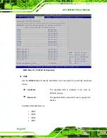
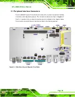
Figure 5-2: Main Board Layout Diagram (Solder Side)
5.2 Internal Peripheral Connectors
Internal peripheral connectors are found on the motherboard and are only accessible
when the motherboard is outside of the chassis. The table below shows a list of the
peripheral interface connectors on the AFL-08B-N270 motherboard. Pinouts of these
connectors can be found in the following sections.
Connector
Type
Label
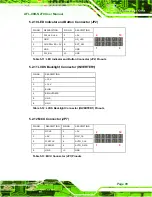
AT/ATX switch connector
2-pin header
JP4
Audio line-out connector
4-pin wafer
CN8
Audio speaker connector
4-pin wafer
CN3
Audio MIC-in connector
4-pin wafer
MIC1
Audio DMIC-in connector
4-pin wafer
DMIC1
Battery connector
2-pin wafer
BT1
CF slot
CF slot
CF1
Содержание AFL-08B-N270
Страница 13: ...AFL 08B N270 User Manual Page 13 Chapter 1 1 Introduction ...
Страница 21: ...AFL 08B N270 User Manual Page 21 Height 177 mm Depth 43 mm Figure 1 6 AFL 08B N270 Dimensions mm ...
Страница 22: ...AFL 08B N270 User Manual Page 22 Chapter 2 2 Installation ...
Страница 52: ...AFL 08B N270 User Manual Page 52 Chapter 3 3 System Maintenance ...
Страница 59: ...AFL 08B N270 User Manual Page 59 Chapter 4 4 BIOS Options ...
Страница 92: ...AFL 08B N270 User Manual Page 92 5 Interface Connectors Chapter 5 ...
Страница 110: ...AFL 08B N270 User Manual Page 110 Appendix A A Safety Precautions ...
Страница 115: ...AFL 08B N270 User Manual Page 115 Appendix B B BIOS Options ...
Страница 118: ...AFL 08B N270 User Manual Page 118 Appendix C C ALC892 Digital Microphone Configuration ...
Страница 122: ...AFL 08B N270 User Manual Page 122 Appendix D D Terminology ...
Страница 126: ...AFL 08B N270 User Manual Page 126 Appendix E E Watchdog Timer ...
Страница 129: ...AFL 08B N270 User Manual Page 129 Appendix F F Hazardous Materials Disclosure ...