


Industrial Electronic Engineers, Inc.
SIZE
A
CODE IDENT NO.
05464
S03858–21–0205
Van Nuys, California
SCALE N/A
REV B
SHEET 6
2.0
LOGICAL STRUCTURE AND FUNCTION
2.1
Module Block Diagram
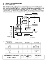
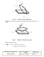
Figure 1 illustrates the major components of the serial option Daystar Nova module. The module provides
means for an external viewing angle adjustment potentiometer (V
BIAS
Adj.) at Pin 4, and connections for optional
RESET and self–test switches at Pins 3 and 5. The external viewing angle adjustment potentiometer should be
connected to the same +5 Volt supply as the display module. RESET and TEST pull down to ground to
activate the function. All three inputs may be left open if not used. The V
BIAS
test point is used at the factory to
preset the viewing angle. The LCD Controllers are microprocessor units (MPU) designed specifically to control
all multiplexing and character decoding functions for the LCD display.
LCD
Controller
#1
LCD
Cell
Column Drivers
LCD
Controller
#2
Column Drivers
Microprocessor
Temperature
Compensation
3
5
8
7
6
4
1
2
10
11
TP
V
BIAS
V
BIAS
Adj
Reset
Test
GND
+5V
R
X
R
X
Rtn
–
+
Serial
Receiver
+5V
View Angle
Adjust
Backlight
Option
EL Backlight
6” Flying Leads
Figure 1
Module Block Diagram
2.1.1
Signal Description
Signal Name
Number Of Lines
Input/Output
Connected
RESET
1
I
MPU
TEST
1
I
MPU
V
BIAS
TP
1
O
Temp. Comp. Ckt.
V
BIAS
Adj.
1
I
Temp. Comp. Ckt.
R
X
1
I
Serial Receiver
R
X
Rtn
1
I
Serial Receiver
V
CC
2
–
Power
GND
7
–
–


