REV: 03-11
DOC1309B
PAGE
3
INSTALLATION INSTRUCTIONS
LC372M REMOTE MICROPHONE MODULE
Control Pin Functions
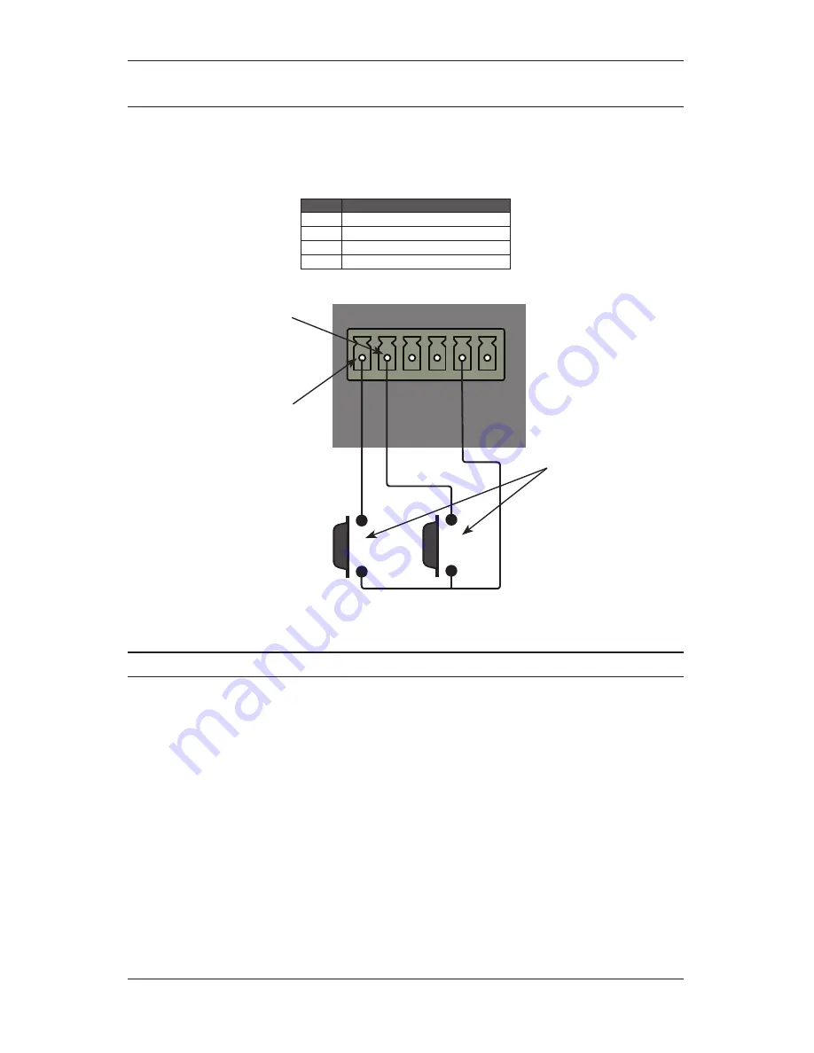
The Auxilliary Connector allows a remote pushbutton switch manufactured by others to be used as a remote call switch
in the system. Each switch must be wired to one of the four available control lines. Multiple buttons can be connected to
the same control line when necessary. The function of each control line is listed in Table 3. The functions may be globally
modified in the LANcom SCS software. Control line 6 is configured in software to perform actions such as closing a relay
that can be used to raise and lower a projection screen or blinds.
Pin
Function
3
Normal intercom call request
4
Emergency intercom call request
5
Lockdown acknowledgement
6
Software-configurable action
Table 3 -
Control Pin Functions
PIN 3
P
IN
4
P
IN
5
P
IN
6
G
N
D
+4
8V
N
O
S
H
U
N
T
=
6
dB
G
A
IN
50
d
B
26
d
B
J2
J1
Pushbutton
Switches
Wired to make
normal intercom call
requests
Wired to make
emergency intercom
call requests
Figure 3 -
Pushbutton Switch Wiring
Specifications
Mechanical
Dimensions ...................................................... 4.5” W x 4.5” H x 1.06” D (114.3mm W x 114.3mm H x 27mm D)
Projection in Front of Plate ............................................................................................................ 0.013” (32mm)
Mounting Depth ............................................................................................................................. 1.00” (25.4mm)
Mounting Box ..............................................................................................................................2-Gang Deep Box
Recommended Electrical Box .......................... Steel City 52151-1/2-3/4 (4” x 4” Box) with 53151-1/2 Extension
Electrical
Power ...........................................................................................................................................48VDC, 12.5 mA
Max. Audio Output .....................................................................................................................................+27dBu
THD .................................................................................................................................................<= 0.0033%
Frequency Response ............................................................................... -3dB @ 75Hz – 10kHz, -20dB @ 20kHz
Gain (Jumper Selectable) ...................................................................................... +52.7dB, +27.5dB or +6.6dB
S/N @ 53dB gain (+24dBu output) .............................................................................................................. 89dB
S/N @ 26dB gain (+24dBu output) ............................................................................................................. 110dB
S/N @ 6dB gain (+24dBu output) ............................................................................................................... 120dB
Connectors
Power and Audio Out...................................................................................................................................... RJ45
Connects to LC372SR or LC331IC using CAT5 or better
** Do not use an RJ45 boot in the box at the module end **


