


10
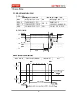
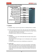
9. Wire Connection to Access Controller
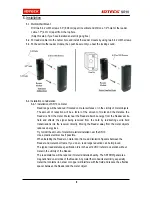
10. Operation
10-1. Apply power and you can see the 3-Array red LED is on, indicating the reader is on ‘Standby ’.
10-2. Present a proximity card to the reader until you hear a beep sound and the LED changes the
color to green simultaneously and the reader sends the RF card data to the controller. Then the
LED changes the color to red again for next reading.
All 3 LEDs are off when you have access to card and then are on orderly from left.
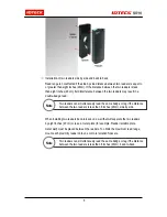
10-3. LED Control:
To be off the LEDs, you may connect the LED Control Input (Yellow wire) to the power ground.
Then the green LED is on.
Present a proximity card. The LED changes the color to red simultaneously, then to green again
for next reading.
All 3 LEDs are off when you have access to card and then are on orderly from left.
10-4. Buzzer Control:
When the reader reads a proximity card, only one beep sound generates in normal operating
mode but you can generate more beep sounds to distinguish whether the access is granted or
denied. To generate more beeps, you may control the Beeper Control Input (Blue wire) to the
power ground, then you can turn the beeper on while you hold the Beeper Control Input to the
power ground.
Red
Black
Orange
Green
White
Blue
Yellow
Gray
Purple
Brown
Access Controller
Main Power (+12V)
Power Ground (GND)
ABA Track II CP Out
Wiegand Data 0 Out /
ABA Track II Data Out
Wiegand Data 1 Out /
ABA Track II Clock Out
Buzzer Control In
LED Control In
34/26bit Wiegand Select In
RS232 (TX)
Not Connect
Содержание Star SR10
Страница 1: ...User s Manual 13 56MHz Contactless Smart Card Reader ...
Страница 14: ...14 MEMO ...
Страница 15: ...15 MEMO ...