Confidential Information - Do Not Distribute
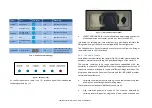
Label
Part
LED color
Meaning
SENSOR
Radar Sensor
solid
Related part powered
POS
Pointing motors
solid
Related part powered
CAMERA
Panoramic and
Pointing camera
solid
Related part powered
GPS
GPS
solid
Related part powered
HEATER
Low temperature
kit
solid
Related part powered
TRANSPORT
Transport mode
solid
Green when the system can
be moved. Red when the
system cannot be moved
Tab. 1 – Positioner LEDs meanings
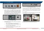
Fig. 10 – Positioner LEDs
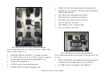
At the Positioner base there is an I/O Interface panel that included the
following sockets (
Fig. 11 – I/O interface Positioner panel
SOCKET POSITIONER: this socket allows the power supply and control
of the acquisition unit (sensor, positioner, cameras and GPS)
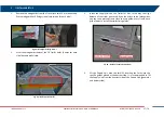
Just below the rotating arm, two metal bars are provided to facilitate the
lifting and moving of the Positioner during ArcSAR first configuration.
The Positioner base has holes placed at every corner to allow the fixing of
the whole frame to the Trailer deck.
4.2.5
Panoramic Camera
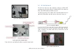
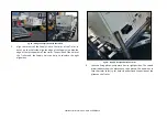
Fixed below the radar trolley the camera (Fig. 14) rotates accordingly to the
positioner movement, providing 360° geocoded images of the scenario.
The camera combines long range surveillance capabilities with the
possibility to acquire 16 Mpixel pictures that are single panoramic views of
the entire scenario, arranged in layers of different image resolution. The
integration between the Panoramic Camera and the IBIS-ArcSAR provides
several additional features:
correlate the picture scenario with a given Guardian radar map, thus
enabling the visual recognition of moving areas;
These features are made possible thanks to the use of:
high resolution panoramic views of the scenario, obtained by
stitching several images in a single one. Views can be acquired on a


