iDM TERRA AL 60 Max Скачать руководство пользователя страница 34

(C) IDM Energiesysteme GmbH

6. General description

Installation instructions TERRA AL 60 Max

34

Electrical connections

6.5. Assigning the inputs on the central unit

The assignment of inputs on the central unit is shown 
in the electric circuit diagram relating to the system.

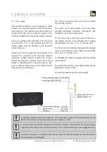
6.6. Confi guration of sensors

Sensor lines are furnished as standard with a line 
cross-section of 0.75 mm².

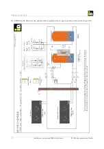
The sensor positions are shown in the respective 
installation layout. A perfect function can only be 
guaranteed by a correct position and optimal thermal 
transition (heat-conductive paste).

If necessary, the sensors can be extended by using 
suitable cabling. Ensure a clean corrosion-free con-
nection.

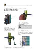
6.8. Flow temperature sensor

The 

fl

 ow temperature sensor for the heating circuits 

used are in any case essential. They are mounted to 
the appropriate 

fl

 ow lines and connected according to 

the connection diagram.

The 

fl

 ow sensors for the heating circuits C-G are con-

nected to the respective heat circuit extension mod-
ule. (see assembly instructions extension module)

The loading sensor (B45) is necessary when the 
heatpump is switchen the priority valve (M63).

6.9. Confi guration of outputs

The detailed con

fi

 guration of outputs on the central 

unit is derived from the electric circuit diagram relat-
ing to the system.

6.10. Connecting the mixers

The ESBE mixers are connected three-pole accord-
ing to the circuit diagram.

Mixer open = brown
Mixer closed = black

6.11. Grounding the system

If the protective conductor is connected properly that 
means that the control panel and the housing of the 
heat pump are grounded properly. 

In the case of maintenance operations, ensure that 
the potential equalization is restored properly once 
the maintenance has been 

fi

 nished.

The sensor lines must be laid separately 
from the feed lines. (see EMC problems)

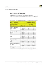
6.7. Sensor confi guration

The following sensors are included in the delivery 
contents. Depending on the system design following 
sensors have to be installed. 

- Space heating storage tank sensor (B38)
- Cooling bu

 er sensor (B40)

- Domestic hot water heating sensor buttom  (B41)
- Domestic hot water heating sensor top  (B48)
- Loading sensor (B45)
- Flow sensor heating circuit A (B51)
- Fresh water station sensor (B42)
- Outer sensor (B32)


The sensors have to be set as shown on the piping 
schemes.

Together with each heat pump a standard 
sensor set is supplied. This is included 
and stored in the control cabinet of the 
heat pump.

Содержание TERRA AL 60 Max

Страница 1: ...AL DOCUMENTATION INSTALLATION INSTRUCTIONS Air water heat pumps for outdoor installation HEAT PUMPS FROM AUSTRIA www idm energie at TERRA AL 60 Max with NAVIGATOR 2 0 Controler 812576 Rev 3 Translatio...

Страница 2: ...16 Scope of delivery 7 1 17 Accessories 7 2 TECHNICAL DATA 8 2 1 Dimensions TERRA AL 60 Max 8 2 2 Dimensions electrical cabinet 8 2 3 Technical data 9 3 DIMENSIONING 11 3 1 Heat output at different ow...

Страница 3: ...ELECTRICAL CONNECTION 31 6 1 Power supply 31 6 2 Connection diagram for the electric components 32 6 3 EMC compatibility 33 6 4 Lightning protection and potential compensation 33 6 5 Assigning the in...

Страница 4: ...r dusty environments The transport fixtures as described in the following assembly instructions are used to transport the heat pump manually The transport fixtures must not be used for transporting th...

Страница 5: ...f the indoor parts loading pump electrical cabinet in wet or damp environ ments or in areas exposed to dust or explosion hazards is non permissible In the case of danger leave the installation site im...

Страница 6: ...ing circles can be con trolled The TERRA AL 60 Max is filled with the safety refrig erant R410A The NAVIGATOR control includes an internal heat metering This means there are no lon ger additional flow...

Страница 7: ...ion valves 2 x Finned tube Al Cu evaporator package 2 x Speed controlled axial fan copper welded stainless steel plate heat exchanger as condenser 2 x switching valve for cooling or defrosting 2 x ini...

Страница 8: ...x3270x920 weigth kg 880 refrigerant side kg 570 evaporator side kg 310 570 kg 310 kg 1500 535 920 900 3270 560 696 654 56 190 Dimensions HxWxD mm 654x560x190 weigth kg Technical data 2 Technical data...

Страница 9: ...C 4 43 COP at A 7 C W35 C 2 88 COP at A2 C W35 C 1 compressor 3 50 COP at A7 C W35 C 1 compressor 4 41 Performace data cooling Cooling capacity at A35 C W18 C kW 70 52 Cooling capacity at A35 C W7 C k...

Страница 10: ...x 17 80 GWP3 1924 Quantity of compressor oil Emkarate TM TL32HB 160SZ 160Z lt 2 x 3 3 1 TERRA AL Max heat pumps work with the by the Kyoto protocol detected safety refrigerant R410A with a global war...

Страница 11: ...TERRA AL 60 Max 11 t t t t t t t t Dimensioning 3 2 Heat output at different ow temperatures and partial load 1 stage 3 Dimensioning outdoor temperature C 3 1 Heat output at different ow temperatures...

Страница 12: ...bivalence exists and is configured in the navigator bivalence mode will start 20 15 10 5 0 5 10 15 20 25 30 35 20 25 30 35 40 45 50 55 60 10 C C 40 45 62 R410A g outdoor temperature ow temperature 0 5...

Страница 13: ...requirements The heat pump must be positioned so that there is su cient space for air intake and air outlet see minimum distances for exterior installation It should not be possible for the inlet and...

Страница 14: ...vel is continuously decreasing with in creasing distance from the noise source to receiver location Doubling the distance leads to a reduction of the sound pressure level of 6 dB A Besides the di stan...

Страница 15: ...are applied information incorporation 0 3 or 6 dB impulsiveness 0 3 or 6 dB daytimes with increased sensitivity 6 dB The rating level Lr shall be obtained by summing the calculated immission level an...

Страница 16: ...e focus On the heatpump you find stickers marking the focus focus Placement and Installation 4 7 Transport IWhen placing the heat pump on site the transportation crate must not be removed The heat pum...

Страница 17: ...Installation 4 8 Placing the heat pump on site When the heat pump is loacated on its final site the crate can be removed The standing feet are turned up wards and the pallet is removed Subsequently t...

Страница 18: ...gher the the surrounnding area If the base is lower than the expected snow level the suction must be kept free of snow snowfall The maximum length of the hydraulic interconnections between Hygienik or...

Страница 19: ...AL 60 Max 19 925 3260 200 200 2860 The ground must be a firm and level surface It is possible to install concrete bases or other good bearing components The load capacity must be guaranteed Placement...

Страница 20: ...n installing in windy areas eg on the roof the orientation of the machine must be selected in such a way that the expected wind direction is turned by 90 degrees to the suction exhaust direction of th...

Страница 21: ...60 Max heat pumps When positioning as shown in example two there are only 2 heat pumps possible The minimum distances must be respected because of the case of maintainance and to prevent air short cir...

Страница 22: ...radius 25 mm 800 mm min 200 mm heating side connectio condensation run off Well pipe 300 mm electrical connections Canalisation concrete base concrete base Placement and Installation Special actions h...

Страница 23: ...deposit in the condenser and lead to a capacity loss of the heat pump or high pressure disturbances Therefore avoid open heating systems or steel pipe installations in conjunction with non di usion re...

Страница 24: ...tifreeze outside tem perature and the fl ow temperature of the heat pump below the minimum temperature the charge pump starts until the pipelines are again on temperature If the heat pump should be st...

Страница 25: ...30 minutes only at commis sioning necessary Switch o the heat pump charging pump Close the wing handle on the ball valve Open the screw connection at the bottom Remove and clean the filter Replace th...

Страница 26: ...on for installing an IDM heat pump in the heating system This suggestion replaces no professional planning of an executing companie On part of IDM Energiesysteme can no warrenty be taken concerning th...

Страница 27: ...a tentative suggestion for installing an IDM heat pump in the heating system This suggestion replaces no professional planning of an executing companie On part of IDM Energiesysteme can no warrenty be...

Страница 28: ...for installing an IDM heat pump in the heating system This suggestion replaces no professional planning of an executing companie On part of IDM Energiesysteme can no warrenty be taken concerning the f...

Страница 29: ...talling an IDM heat pump in the heating system This suggestion replaces no professional planning of an executing companie On part of IDM Energiesysteme can no warrenty be taken concerning the function...

Страница 30: ...mp in the heating system This suggestion replaces no professional planning of an executing companie On part of IDM Energiesysteme can no warrenty be taken concerning the function of the whole system G...

Страница 31: ...pump must be 400 V 10 The dimensions of the con necting cables must be checked by the executive electric company A fault current circuit breaker for the heat pump is not required The connection to th...

Страница 32: ...F10 F9 F3 F7 F6 F1 F2 F5 X42 X2 X4 ON 2 1 ON 2 1 H4 H5 H6 H7 H3 H2 H1 S1 S2 X3 1 2 X6 X11 X8 X7 X5 K2 X10 X9 K3 K4 K1 79 H L X1 Touchdisplay X1 Extension module internal I O 28 0 DIP Switch for RS Te...

Страница 33: ...visible The disturbances can have various e ects Short term measurement errors Long term measurement errors Short term interruption of data connections Long term interruption of data connections Data...

Страница 34: ...hen the priority valve M63 6 9 Configuration of outputs The detailed configuration of outputs on the central unit is derived from the electric circuit diagram relat ing to the system 6 10 Connecting t...

Страница 35: ...sed contact of a zone valve is generated If zone valves are used a sum signal of all zone valves can be generated to be able to switch the heating and cooling circuit ON resp OFF with the thermostat f...

Страница 36: ...eating side in a frost proof mode the connection hose has to be loosened at the heat pump return plate heat exchanger 7 2 Switching the heat pump on for the very first time After pressing the main swi...

Страница 37: ...24 26 1 55 20 37 86 16 98 2 23 36 70 20 39 1 80 36 20 23 35 1 55 37 39 26 90 1 39 A C Q kW P kW COP Q kW P kW COP Q kW P kW COP Q kW P kW COP 20 49 92 9 11 5 48 45 83 10 81 4 24 42 31 12 50 3 38 40 20...

Страница 38: ...e 35 C 55 C Cold A A Average A A Warm A A Cold 118 94 Average 136 112 Warm 165 133 Cold 3 02 2 43 Average 3 47 2 87 Warm 4 20 3 39 Cold 47 47 Average 55 54 Warm 54 51 Cold 38 411 47 882 Average 32 619...

Страница 39: ...ZLOO UHQGHU WKLV GHFODUDWLRQ LQYDOLG 8 LUHFWLYHV RZ 9ROWDJH LUHFWLYH 8 0 LUHFWLYH 8 FRGHVLJQ LUHFWLYH 8 3UHVVXUH TXLSPHQW LUHFWLYH 8 8 52 6 LUHFWLYH 8 8 5HJXODWLRQ 5HJXODWLRQ RQ IOXRULQDWHG JUHHQKRXVH...

Страница 40: ...SITE SERVICE OUR SERVICE TECHNICIANS ARE HAPPY TO HELP ON SITE CONTACT DETAILS FOR YOUR REGIONAL CUSTOMER SERVICE CENTRE CAN BE FOUND ON OUR WEBSITE iDM Akademy PRACTICAL KNOWLEDGE FOR SALES AND TECH...

Отзывы: