background image

T E C H N I C A L   D O C U M E N TAT I O N 

I N S TA L L AT I O N   I N S T R U C T I O N

HEAT PUMPS FROM AUSTRIA 

www.idm-energie.at

812571_Rev

.0 - 

T

ranslation of original instruction

EIB/KNX

Navigator Control 2.0

Содержание EIB/KNX

Страница 1: ...TECHNICAL DOCUMENTATION INSTALLATION INSTRUCTION HEAT PUMPS FROM AUSTRIA www idm energie at 812571_Rev 0 Translation of original instruction EIB KNX Navigator Control 2 0...

Страница 2: ...on 6 3 2 Scope of delivery 6 3 3 Installation 6 3 4 Connecting the EIB KNX module to the Navigator main board 7 3 5 Connecting the EIB bus cable to the EIB KNX module 7 4 PROGRAMMING 8 4 1 Programming...

Страница 3: ...will become void in the event of damage arising as a result 1 4 Environmental Protection Information 1 5 Standards and Guidelines These include the generally accepted accident prevention and safety re...

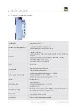
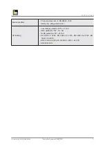
Страница 4: ...t IP tunneling KNX BAOS Binary Protocol V2 0 KNX BAOS Web Services JSON KNX Medium TP Connections Bus terminal for KNX red black LAN connection clamp RJ 45 Ambient temperature range Ambient temperatur...

Страница 5: ...trical safety Protection class acc to EN 60529 IP 20 Safety low voltage SELV 29V CE labeling Low voltage guideline 2014 35 EU EMC guideline 2014 30 EU RoHS guideline 2011 65 EU EN 50491 3 2009 EN 5049...

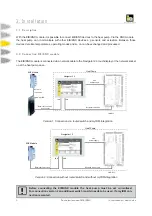
Страница 6: ...e The EIB KNX module is connected via a network cable to the Navigator 2 0 touchdisplay or the network socket on at the heat pump case Before connecting the EIB KNX module the heat pump must be set cu...

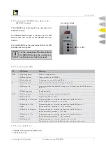
Страница 7: ...valid IP settings on the device LED glowing red Active ethernet link and invalid IP settings or no IP settings from the DHCP server to the device LED flickering green IP telegram traffic Mode LED glow...

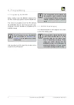
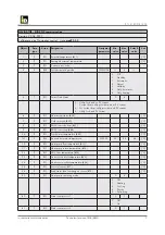
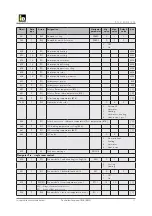
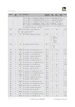
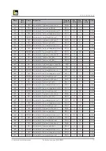
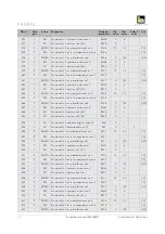
Страница 8: ...o any ETS project 4 2 EIB KNX Objektbelegung The detailed assignment of the objects can be infer red from the following table The configuration of the objects and the module s serial interface should...

Страница 9: ...ent 1 Current from utility provider and no PV current 2 No current from utility provider and PV current 4 Utility lock and PV current 6 9 RO Heat accumulator B38 C 7 9 RO Cold reservoir B40 C 8 9 RO D...

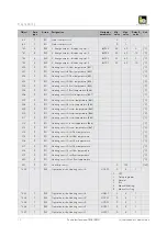
Страница 10: ...room temperature B61 C 208 9 RO Heating circuit B room temperature B62 C 209 9 RO Heating circuit C room temperature B63 C 210 9 RO Heating circuit D room temperature B64 C 211 9 RO Heating circuit E...

Страница 11: ...HC F HCF05 10 25 18 C 242 9 RW Set room temperature heating eco HC G HCG05 10 25 18 C 243 9 RW Heating curve HC A HCA10 0 1 3 5 1 2 244 9 RW Heating curve HC B HCB10 0 1 3 5 1 2 245 9 RW Heating curve...

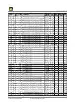
Страница 12: ...C B HCB58 0 36 25 C 280 7 RW Cooling limit HC C HCC58 0 36 25 C 281 7 RW Cooling limit HC D HCD58 0 36 25 C 282 7 RW Cooling limit HC E HCE58 0 36 25 C 283 7 RW Cooling limit HC F HCF58 0 36 25 C 284...

Страница 13: ...lar collector temperature B73 C 451 9 RO Solar collector return temperature B75 C 452 9 RO Solar loading temperature B74 C 453 7 RW Operation mode solar 0 4 0 0 Automatik 1 Hot water 2 Heating 3 Hot w...

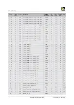
Страница 14: ...e 1 room temperature zone 2 RT1 2 15 30 C 508 9 RW Zone module 1 set room temperature zone 2 RS1 2 C 509 7 RW RO Zone module 1 room humidity zone 2 RF1 2 0 100 rF 510 7 RW Zone module 1 operation mode...

Страница 15: ...one 1 RT2 1 15 30 C 550 9 RW Zone module 2 set room temperature zone 1 RS2 1 C 551 7 RW RO Zone module 2 room humidity zone 1 RF2 1 0 100 rF 552 7 RW Zone module 2 operation mode zone 1 RM2 1 0 4 553...

Страница 16: ...module 2 operation mode zone 8 RM2 8 0 4 588 7 RO Zone module 2 status zone 8 A8 RR2 8 0 1 593 7 RO Zone module 2 status zone 9 A9 RR2 9 0 1 594 7 RO Zone module 3 mode heating cooling A14 ZM3 0 1 59...

Страница 17: ...e 3 operation mode zone 7 RM3 7 0 4 630 7 RO Zone module 3 status zone 7 A7 RR3 7 0 1 631 9 RW RO Zone module 3 room temperature zone 8 RT3 8 15 30 C 632 9 RW Zone module 3 set room temperature zone 8...

Страница 18: ...odule 4 room temperature zone 6 15 30 C 669 9 RW Zone module 4 set room temperature zone 6 C 670 7 RW RO Zone module 4 room humidity zone 6 0 100 rF 671 7 RW Zone module 4 operation mode zone 6 0 4 67...

Страница 19: ...C IDM ENERGIESYSTEME GMBH Technical manaul EIB KNX 19 D I E E N E RG I E FA M I L I E Programmierung Programmierung...

Страница 20: ...ration EIB KNX Modul in the Navigator control For EIB KNX communication it is necessary the do the following settings within the service level of the Navi gator control In the main menu Settings choos...

Страница 21: ...KNX room sensor in the Navigator control If one or more EIB KNX room sensors are used they have to be configured in the Navigator control Therefore the following settings have to be done in the servi...

Страница 22: ...th IDM single room control If the IDM single room control and EIB KNX sensors are used it is necessary to configure them within the Navigator control service level Therefore the following settings hav...

Страница 23: ...d room with KNX Configurate the room name and corresponding set tings and confirm with execute 5 4 Error messages Within the Navigator control and preconfigured EIB KNX module the error message KNX mo...

Страница 24: ...VICING ON SITE SERVICE Our service technicians are happy to help on site Contact details for your regional customer service centre can be found on our website iDM Akademy PRACTICAL KNOWLEDGE FOR SALES...

Отзывы: