


Part 1 – Introduction
10
Overview
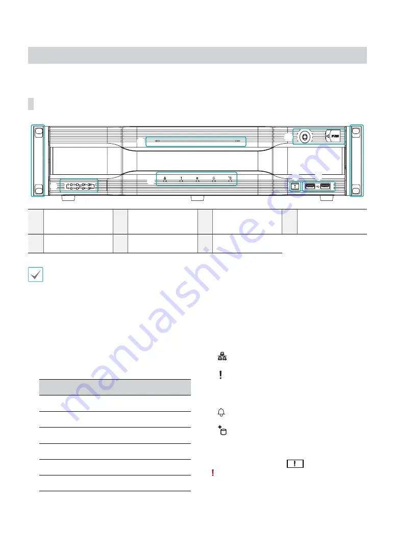
Front Panel
1
SATA LED
2
Status LEDs
3
Panic Recording
Button
4
USB Ports
5
Power LED
6
Front Door Lock
7
Rack Mount Ears
•
Some buttons have more than one function.
•
Remote control sensor is located on the left side of the front panel. Ensure that the sensor remains unobstructed at all
times. If obstructed, the sensor might not be able to receive remote control signals.
•
Placing a Wi-Fi, Bluetooth, or any other wireless communication device near the NVR may interfere with remote control
signal transmission.
•
Access various windows and menus using a USB mouse as you would on a personal computer.
•
For easier system configuration, a USB mouse is recommended.
1
SATA LED
These LEDs indicate the status of HDD and RAID
mode.
LED
Color
HDD Status
On
Green
SATA HDD Connection
Blinking
Green
Data Transmission
On
Red
RAID Broken
Blinking
Red
RAID Rebuilding
On
Green / Red
HDD / RAID Error
Off
-
No SATA HDD
2
Status LEDs
●
Network LED
: Flashes when the main unit is
linked to an ethernet.
●
Panic LED
: Flashes in red when Panic Recording
is in progress.
●
R LED
: Lights up in red when RAID mode is
operating nomally.
●
Alarm LED
: Lights up in red when an alarm
event occurs.
●
eSATA LED
: Lights up when the main unit is
connected to an eSATA device.
3
Panic Recording
Button
Pressing
Panic Recording
1
2
3
4
5
6
7
8
9
0
button displays the
icon and commences recording irrespective of the
current schedule.
Press the button again to deactivate Panic Recording
mode.
1
2
3
4
6
5
7
7
Содержание DR-8516
Страница 1: ...Powered by Network Video Recorder Installation Manual DR 8516 DR 8532 DR 8532D ...
Страница 12: ...Part 1 Introduction 12 Connections on the Front Panel IR Remote Control Flash Memory Mouse USB HDD ...
Страница 28: ...IDIS Co Ltd For more information please visit at www idisglobal com ...


