Part 1 – Introduction
14
Rear Panel Connections
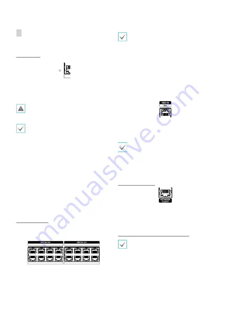
Factory Reset
Located left next to the Video In / PoE port on the rear of
the NVR is a switch that, once activated, will reset the NVR
to all its initial factory settings.
A factory reset will clear all NVR settings configured by
the user.
You will need a straightened paper clip to access the
factory reset button.
1
Turn off the NVR.
2
Insert a straightened paper clip into the factory reset
switch hole and press the switch. Turn on the NVR
while holding the switch.
3
Press and hold until you hear 2 beeps from the NVR's
internal buzzer.
4
All NVR settings will be returned to their factory
values once you remove the paper clip.
Video Connection
●
Video In/PoE Port
1
3
5
7
2
4
6
8
9
11
13
15
10
12
14
16
Connect network cameras or video encoders to the
NVR using RJ-45 cable (Cat5e, or Cat6). In addition to
cameras or video encoders, you can connect external
hubs (Optional: DH-2112PF, DH-2128PF) to form a
network. The NVR recognizes DirectIP™ network cameras
automatically. Ports 1 through 16 support PoE.
•
We recommend that you use the Ext. port for
connecting to an external hub and using features
such as camera alignment.
•
Green LED on the right will turn on when PoE comes
on line. Orange LED on the left will then flash once a
link has been established.
•
If more than 16 cameras from video encoders are
registered on the NVR, video may not be displayed
smoothly in a remote program.
●
Video In / Ext. Port
This port does not support PoE. It's possible to establish a
network with network cameras and external hubs using
a Cat6 cable.
•
Green LED on the right will turn on if connected to
a 1000 BASE-T network. Orange LED on the left will
then flash once a link has been established.
•
When using a Cat5e cable, the data transfer speed
may decrease depending on how to establish a
network.
Network Connection
This NVR is capable of connecting to networks via an
ethernet connector. Connect an RJ-45 cable (Cat5e, or
Cat6) to the NVR's network port. It's possible to operate
and upgrade the NVR remotely over a network. Fore
more information on ethernet connection setup, refer to
Network Setup in the operation manual
.
•
Connector directions may vary depending on the
NVR model.
•
Green LED on the right will begin to flash if
connected a 1000 BASE-T network. Orange LED
on the left will then flash once a link has been
established.
Содержание DR-4308P
Страница 1: ...Powered by Network Video Recorder Installation Manual DR 4308P DR 4316PS...
Страница 11: ...Part 1 Introduction 11 Connections on the Front Panel IR Remote Control Flash Memory Mouse USB HDD...
Страница 12: ...Part 1 Introduction 12 Dimensions Unit mm 88 94 5 430 420 5 413 8...
Страница 28: ...IDIS Co Ltd For more information please visit at www idisglobal com...


