


Part 1 – Introduction
13
Rear Panel Connections
For simplicity, the illustrations and descriptions in the
rear panel connections refer to the DR-1308P model.
Monitor Connection
Connect to the
VGA OUT
or
HDMI
port.
Network Connection
This NVR is capable of connecting to networks via an
ethernet connector. Connect an RJ-45 cable (Cat5,
Cat5e, or Cat6) to the NVR's network port. It's possible to
operate and upgrade the NVR remotely over a network.
Fore more information on ethernet connection setup,
refer to
Network Setup in the operation manual
.
Green LED on the right will begin to turn on if
connected a 100Mbps network. Also, orange LED on
the left will begin to turn on if connected a 10Mbps
network. Orange LED on the left will then flash once a
link has been established.
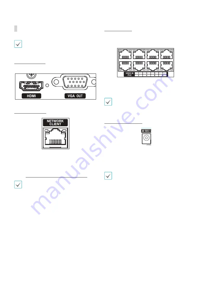
Video Connection
•
Video In/PoE Port
Connect network cameras or video encoders to the
NVR using RJ-45 cable (Cat5, Cat5e, or Cat6). The NVR
recognizes DirectIP™ network cameras automatically.
•
Green LED on the right will turn on when PoE comes
on line. Orange LED on the left will then flash once a
link has been established.
Power Cable Connection
1
6
5
4
3
2
This NVR does not feature a separate power on/off
button and will turn on
the moment power is supplied.
Connect the connector(48-56V) of adapter to the NVR
and then connect the AC power cable of adapter to the
power outlet. (4-channel model: 48V)
•
Organize the power cable so that it will not cause
people to trip over or become damaged from chairs,
cabinets, desks, and other objects in the vicinity. Do
not run the power cable underneath a rug or carpet.
•
Do not connect multiple devices to a single power
outlet.


