


Part 1 – Introduction
9
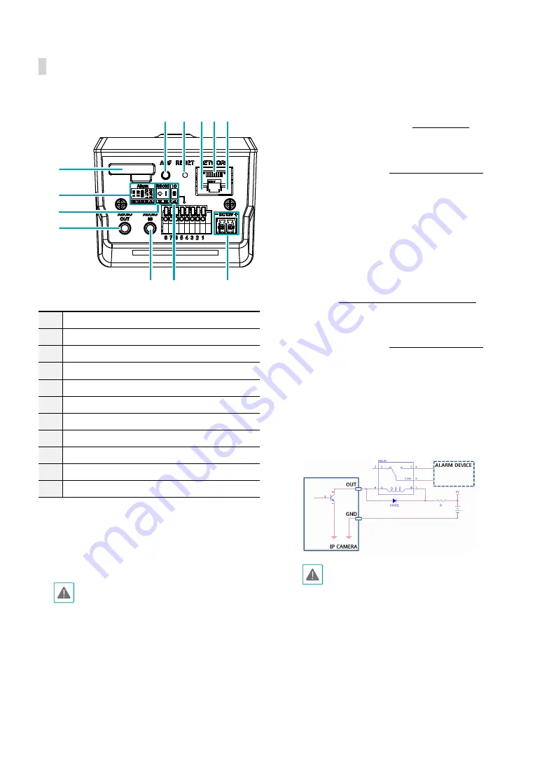
Back
1
2 3456
9
7
8
9 0
!
1
SD Memory Card Slot
2
ABF(Auto Back Focus)
3
Factory Reset Switch
4
Network LED
5
Network Port
6
Power LED
7
Alarm I/O
8
RS485 Port
9
Audio I/O
0
IO Port
!
Power
•
SD Memory Card Slot
Pull on the connection cover and then insert a
microSD memory card into the slot. (An SLC (Single
Level Cell) or MLC (Multi Level Cell) card by SanDisk
or Transcend is recommended)
•
Do not remove the SD memory card while the
system is in operation. Removing the card while
the system is in operation can cause the system
to malfunction and/or corrupt data stored on
the SD memory card.
•
An SD memory card is a consumable product
with a finite service life. Prolonged use will
damage the card's memory sectors and result
in data loss or memory card failure. Test the SD
memory card regularly and replace it whenever
necessary.
•
ABF(Auto Back Focus)
Finds the best focus position automatically.
•
Factory Reset Switch
Restores the camera's default factory settings. For
more information, refer to the
•
Network LED
Indicates the network connection status. For more
information, refer to the
•
Network Port
Connect a Cat5e cable with an RJ-45 connector to
this port. If using a PoE switch, you can supply power
to the camera using an ethernet cable. For more
information on PoE switch use, refer to the switch
manufacturer's operation manual. You can configure,
manage, and upgrade this camera and monitor its
images from a remote computer over the network.
For more information on network connection setup,
refer to the
IDIS Discovery operation manual
.
•
Power LED
Indicates the system's operating status. For more
information, refer to the
•
Alarm I/O
-
Out
: It is the BJT (Bipolar Junction Transistor) -
open collector output. If the voltage and current
exceed the specification limit (Max load: 30mA,
Max Voltage: 5VDC), the product could be
damaged. When connecting the device which
exceeds the specification limit, refer to the picture
(circuit) below.
If used with an external inductive load (e.g.
relay), a diode must be connected in parallel
with the load for protection. Otherwise, the
product could be damaged.
-
In
: Connect an alarm-in device to this port.
(Mechanism: Choose between an NC (Normally
Closed) type or an NO (Normally Open) type)
Connect a mechanical or electrical switch to the
alarm in port and the GND (ground) connector.
Alarm in range is 0V to 5V. In order to detect alarm
input from an electrical switch, the signal must be
higher than 4.3V from an NC switch or less than
0.3V from an NO switch and must last for longer
than 0.5 seconds.
Содержание DC-B6203XL
Страница 1: ...Powered by DC B Series Installation Manual DC B6203XL ...
Страница 19: ......
Страница 20: ...IDIS Co Ltd For more information please visit at www idisglobal com ...