


REV6 OPERATION / MAINTENANCE MANUAL
24
CONTENTS
Item
Interface
Description
5
“Power on” Green LED
LED is on if supply voltage of signal electronics is present.
6
“Power Output not
active” Red LED
Red LED is off if the switched output stage of the controller is enabled. If the LED is on, the
bearing and drive coils of the motor carry no current.
7
“RESET” Button
Reset button of the controller stage. The button is recessed and can be activated using a
small pointed object.
8
2-Digit Display “Speed”
Rotational speed display in 100 RPM
9
“UP” Button
Button for speed increasing
10
“DOWN” Button
Button for speed decreasing
11
“Firmware” Label
Firmware version and revision number
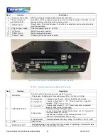
Figure 22 – Overview of the Standalone Controller Interface
Table 8 – Interface Description of Extended Controller
Item
Interface
Description
1
“SENSORIC”
Position, field and temperature sensor signals from motor
Torque spec. for tightening of connector screws: Min. = 0.4, Max. = 0.6 Nm
2
“USER INTERFACE”
2 Analog Input
- Analog current input: 4 – 20 mA - 450 Ohm shunt input
2 Analog Input
- Analog voltage input 0 – 10 V - Direct connection, no galvanic
isolation - 7.8 k
input re s is ta nce
2 Analog Output
- Analog voltage output: 0 – 5 V - Direct connection, no galvanic
isolation - Max. Output current: 2mA
4 Digital Input
- Galvanic isolation with optocoupler
- Lowest input voltage for high level detection: min. 5 V Typical 24 V /
16 mA, maximal 30 V / 20 mA
- Highest input voltage for low level detection: max. 0.8 V
- Minimum input resistance: RIN = 2.2 k
4 Digital Output
- Galvanic isolation with relay - Relay: 1A / 30VDC, 0.3A / 125 VAC
3
“USB”
USB interface
4
“POWER OUTPUT”
Drive and bearing currents of the motor. Torque spec. for tightening of connector screws
on motor side: Min. = 0.5 Nm, Max. = 0.6 Nm