


FC6A S
ERIES
MICROS
MART
L
ADDER
P
ROGRAMMING
M
ANUAL
FC9Y-B1726
18-27
18: P
ULSE
O
UTPUT
I
NSTRUCTIONS
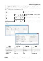
RAMPL (Linear Interpolation Control)
The RAMPL instruction outputs pulses with a frequency change function that operates simultaneously from two outputs, so that
the trajectory of movement is linear.
This instruction can be used with the Plus CPU module transistor output type and CAN J1939 All-in-One CPU module transistor
output type.
Ladder Diagram
Operation
When the input is on, the initial pulse frequency and steady pulse frequency are calculated from the preset value specified by S1
(target position), the combined initial pulse frequency, and the combined steady pulse frequency, so that the trajectory of
movement is linear. Then the pulses are simultaneously output from the two specified outputs, and the pulse frequency increases
at a constant rate until the frequency reaches the steady pulse frequency of the axes. After pulses of a constant speed are output
at the steady pulse frequency, the pulses frequency decreases before reaching the preset value specified by S1, and then the pulse
output stops when it reaches the preset value.
When the initialization input specified by S2 is turned on, the initial values configured in the WindLDR
RAMPL (Ramp Pulse
Output with Liner Interpolation)
dialog box, on the
Common Settings
tab, are stored in the control registers.
The control status, including the pulse output status (output on/output direction/output complete), is stored in the operation
status specified by D1.
Notes:
•
If a pulse output instruction is simultaneously executed with the same output, a user program execution error will occur.
Error code 48 will be stored in D8006 and instructions that are executed later will be canceled.
•
The RAMPL instruction cannot be used in an interrupt program. If used in an interrupt program, a user program execution error will occur.
Error code 18 will be stored in D8006 and instruction execution will be canceled.
•
If a pulse output instruction is executed with the relay output type, a user program execution error will occur.
Error code 19 will be stored in D8006 and instruction execution will be canceled.
•
The RAMPL instruction operates only in absolute position mode with accompanying reversible control. After starting operation of the ladder
program, execute the ABS instructions that correspond to the specified outputs to initialize the absolute position counters. If the
corresponding absolute position counter initialized flags in D8239 (absolute position control status) are 0 (not initialized), a user program
execution error will occur when the instruction is executed.
•
For user program execution errors, see "User Program Execution Errors" on page 3-10.
Valid Devices
*1 Special data registers cannot be used.
*2 Special internal relays cannot be used.
D1
*****
S2
*****
RAMPL
12
S1
*****
X axis preset value
Y axis
preset value
Y axis
X axis
X axis steady
pulse frequency
X axis preset value
Y axis preset value
Y axis steady
pulse frequency
Frequency increase time
Frequency increase and decrease times are the same
Trapezoid area = Preset value
Frequency decrease time
Device
Function
I
Q
M
R
T
C
D
P
Constant
Repeat
S1 (Source 1)
Control registers
—
—
—
—
—
— X
—
—
—
S2 (Source 2)
Initialization input
X
—
X
—
—
—
—
—
—
—
D1 (Destination 1)
Operation status
—
— X
—
—
—
—
—
—
—
Содержание MICROSmart FC6A Series
Страница 1: ...B 1726 7 FC6A SERIES Ladder Programming Manual ...
Страница 8: ...Preface 7 FC6A SERIES MICROSMART LADDER PROGRAMMING MANUAL FC9Y B1726 ...
Страница 32: ...1 OPERATION BASICS 1 20 FC6A SERIES MICROSMART LADDER PROGRAMMING MANUAL FC9Y B1726 ...
Страница 96: ...3 INSTRUCTIONS REFERENCE 3 18 FC6A SERIES MICROSMART LADDER PROGRAMMING MANUAL FC9Y B1726 ...
Страница 130: ...4 BASIC INSTRUCTIONS 4 34 FC6A SERIES MICROSMART LADDER PROGRAMMING MANUAL FC9Y B1726 ...
Страница 158: ...6 DATA COMPARISON INSTRUCTIONS 6 10 FC6A SERIES MICROSMART LADDER PROGRAMMING MANUAL FC9Y B1726 ...
Страница 192: ...9 SHIFT ROTATE INSTRUCTIONS 9 12 FC6A SERIES MICROSMART LADDER PROGRAMMING MANUAL FC9Y B1726 ...
Страница 216: ...10 DATA CONVERSION INSTRUCTIONS 10 24 FC6A SERIES MICROSMART LADDER PROGRAMMING MANUAL FC9Y B1726 ...
Страница 248: ...11 WEEK PROGRAMMER INSTRUCTIONS 11 32 FC6A SERIES MICROSMART LADDER PROGRAMMING MANUAL FC9Y B1726 ...
Страница 272: ...12 DISPLAY INSTRUCTIONS 12 24 FC6A SERIES MICROSMART LADDER PROGRAMMING MANUAL FC9Y B1726 ...
Страница 284: ...14 REFRESH INSTRUCTIONS 14 6 FC6A SERIES MICROSMART LADDER PROGRAMMING MANUAL FC9Y B1726 ...
Страница 288: ...15 INTERRUPT CONTROL INSTRUCTIONS 15 4 FC6A SERIES MICROSMART LADDER PROGRAMMING MANUAL FC9Y B1726 ...
Страница 294: ...16 COORDINATE CONVERSION INSTRUCTIONS 16 6 FC6A SERIES MICROSMART LADDER PROGRAMMING MANUAL FC9Y B1726 ...
Страница 374: ...18 PULSE OUTPUT INSTRUCTIONS 18 78 FC6A SERIES MICROSMART LADDER PROGRAMMING MANUAL FC9Y B1726 Setting ...
Страница 450: ...20 DUAL TEACHING TIMER INSTRUCTIONS 20 4 FC6A SERIES MICROSMART LADDER PROGRAMMING MANUAL FC9Y B1726 ...
Страница 502: ...25 DATA LOG INSTRUCTIONS 25 22 FC6A SERIES MICROSMART LADDER PROGRAMMING MANUAL FC9Y B1726 ...
Страница 546: ...26 SCRIPT 26 44 FC6A SERIES MICROSMART LADDER PROGRAMMING MANUAL FC9Y B1726 ...
Страница 574: ...27 FLOW CALCULATION INSTRUCTIONS 27 28 FC6A SERIES MICROSMART LADDER PROGRAMMING MANUAL FC9Y B1726 ...
Страница 583: ...FC6A SERIES MICROSMART LADDER PROGRAMMING MANUAL FC9Y B1726 28 9 28 USER DEFINED MACRO INSTRUCTION ...
Страница 584: ...28 USER DEFINED MACRO INSTRUCTION 28 10 FC6A SERIES MICROSMART LADDER PROGRAMMING MANUAL FC9Y B1726 ...
Страница 598: ...APPENDIX A 14 FC6A SERIES MICROSMART LADDER PROGRAMMING MANUAL FC9Y B1726 ...


