INSTALLATION
M A N U A L
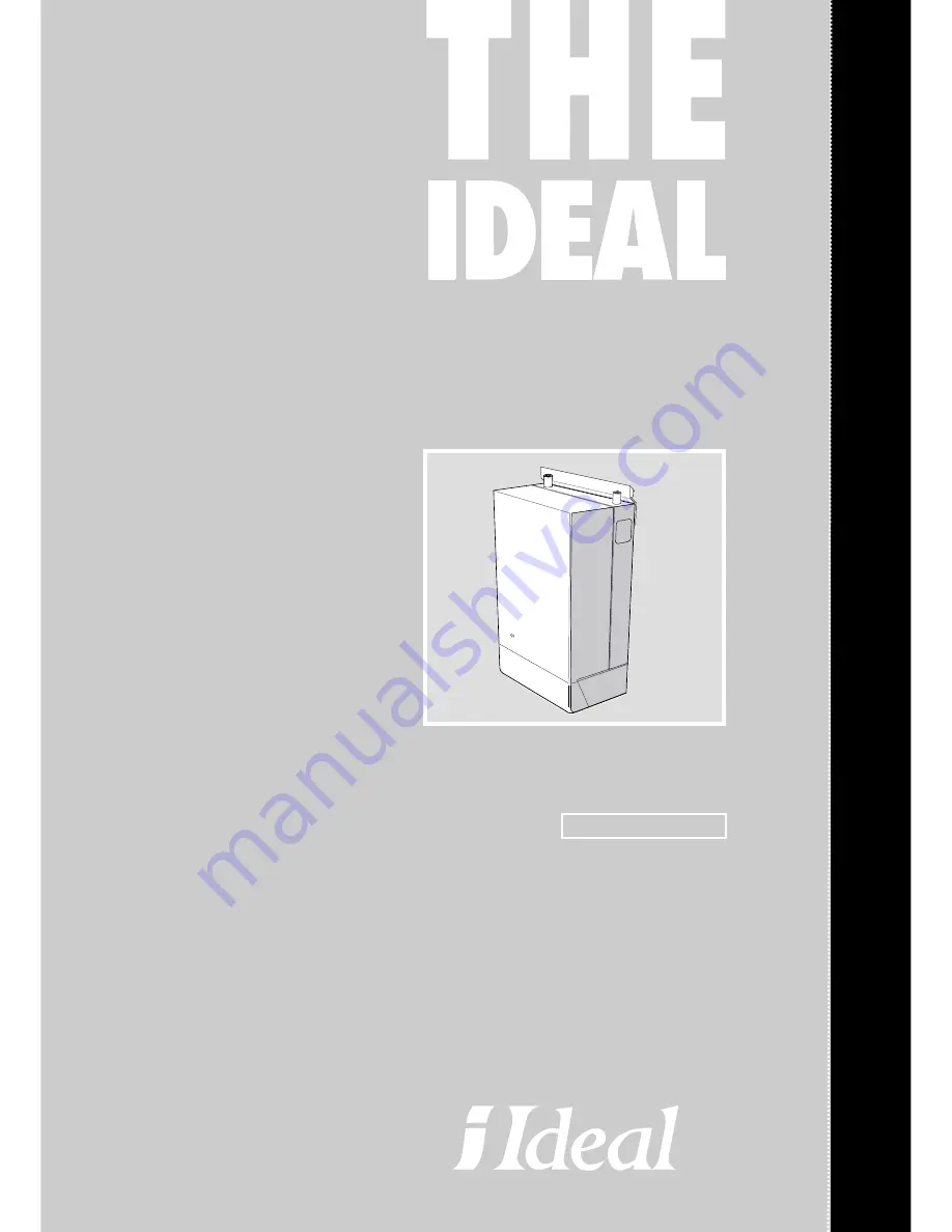
Classic Slimline
the wall hung boiler
Wall hung, fanned flue,
gas fired boiler
FF 230 - 260
Installers guide to central heating boilers
& SERVICING
BOILERS
Страница 1: ...INSTALLATION M A N U A L Classic Slimline the wall hung boiler Wall hung fanned flue gas fired boiler FF 230 260 Installers guide to central heating boilers SERVICING BOILERS...
Страница 2: ...n this case are concentric The fan is down stream of the combustion chamber I2H An appliance designed for use on 2nd Family gas Group H only Data Badge on top of the controls support B G Certified P I...
Страница 3: ...input Btu h by the gross C V of the gas Btu ft3 Table 1 General Data Table 2 Performance Data The value is used in the UK Government s Standard Assessment Procedure SAP for energy rating of dwellings...
Страница 4: ...nvalidate the certification and the normal appliance warranty It could also infringe the Gas Safety Regulations and the above regulations SAFE HANDLING OF SUBSTANCES Care should be taken when handling...
Страница 5: ...fit or remove the casing during installation and subsequent servicing is impaired by pelmets etc this operation can be made easier by first removing the controls pod casing in line with the following...
Страница 6: ...l air 2 It is important that the position of the terminal allows the free passage of air across it at all times 3 Minimum acceptable spacing from the terminal to obstructions and ventilation openings...
Страница 7: ...ter supply For the types of system and correct piping procedure refer to Introduction and Frame 1 The central heating system should be in accordance with BS 6798 and in addition for Smallbore and Micr...
Страница 8: ...mestic circulator capable of providing an 11 C 20 F temperature differential e g Grundfos UPS 15 50 or equivalent The vertical distance between the pump and feed expansion cistern MUST comply with the...
Страница 9: ...tween them the stop valve being located between the system and the automatic air vent The stop valve may remain open during normal operation of the system if automatic water make up is required b Thro...
Страница 10: ...e setting 3 0 bar Vessel charge and 0 5 1 0 1 5 initial system pressure bar bar bar Total water content of system Expansion vessel volume litres 25 litres 2 1 2 7 3 9 50 4 2 5 4 7 8 75 6 3 8 2 11 7 10...
Страница 11: ...Classic FF 230 shown LEGEND 1 Heat exchanger 2 Flue baffles 3 Hook bolts 4 Flow pipe assy 5 Return pipe assy 6 Collector hood assembly 7 Combustion chamber 12 Main burner 19 Control box 24 Pressure sw...
Страница 12: ...n frame to ease handling and installation 4 Unpack the boiler terminal box and if applicable the extension flue box es 9 PACKAGING AND CASING REMOVAL SIDE FLUE INSTALLATION REAR FLUE INSTALLATION FLUE...
Страница 13: ...following a The wall mounting plate screw positions choose one from each group Note Mark the centre of the flue hole as well as the circumference b The position of the flue duct hole 5 Remove the tem...
Страница 14: ...aligns with the groove on the outer flue duct This ensures correct alignment of the flue terminal 4 Stick the self adhesive foam strip provided in the hardware pack onto the flue immediately behind th...
Страница 15: ...o the wall plug Use the washer and rectangular sealing plate to seal the slot and retain the boiler Note Before fully tightening the retaining screw check the boiler alignment using a spirit level and...
Страница 16: ...insert the plastic plugs provided for the wall mounting plate 3 Drill 1 further hole below the wall plate fixing screws in the position shown on the template for boiler fixing with the same 8mm 5 16 m...
Страница 17: ...the tube is cut square mark the flue all the way round 4 Insert the cardboard duct ring for support and cut to length 5 Remove cardboard duct ring and remove any burrs 26 FITTING BOILER SEALING RING...
Страница 18: ...jacking screw 1 Fix the mounting plate to the wall with the No 14 x 50mm wood screws 2 Check with a spirit level that the plate is horizontal 28 FITTING THE SIDE OUTLET PLATES 30 MOUNTING THE BOILER...
Страница 19: ...5 Pull the flue extension tube and engage onto the fan elbow and secure with the screw attached to the elbow Note The sealing ring studs will locate in the back panel one way only This will ensure th...
Страница 20: ...G THE KIT 1 Remove the cardboard support aid from the flue and place safely to one side 2 Fit the inner flue extension duct onto the inner flue duct 3 Fit the outer flue extension duct onto the outer...
Страница 21: ...ide an on off control e g frost thermostat must be wired into the mains lead in parallel with the control s to be overridden Refer to Frame 43 3 If a proprietary system is used follow the instructions...
Страница 22: ...is a fully controlled system set the boiler thermostat to maximum 4 Switchmaster Midi is similar in operation but the wiring differs slightly see the manufacturer s literature LEGEND b blue bk black b...
Страница 23: ...ill be left off for more than a day or so then a frost thermostat should be wired into the system This is usually done at the programmer in which case the programme selector switches are set to OFF an...
Страница 24: ...by pulling it forward to disengage from the keyhole slots b Remove the control box securing screws and swing it down into the servicing position See diagram B 5 Slacken the screw in the burner pressu...
Страница 25: ...taller you may wish to undertake the service contract yourself or alternatively offer to the customer the benefits of the Caradon Ideal Services details of which are outlined in the household pack sup...
Страница 26: ...this is the case and the gas input is at least 90 of the nominal then no further action need be taken If not proceed to paragraph c c Clean the main burner Refer to Frame 51 d Clean the heat exchanger...
Страница 27: ...pproved jointing compound sparingly 4 Inspect the pilot burner and ignition detection electrode Ensure that they are clean and in good condition Check that a The pilot burner injector is not blocked o...
Страница 28: ...Relight in accordance with Initial Lighting Frame 45 Note In order to assist fault finding the control box printed circuit board is fitted with 2 indicator lights which represent the following boiler...
Страница 29: ...der On off switch 10 Disconnect the electrical connectors from the rear of the switch 11 Press in the 2 side retaining clips and remove the switch 12 Reassemble in reverse order 1 Refer to Frame 56 2...
Страница 30: ...as required Ensure that a new copper sealing washer is used 5 Fit the new burner ensuring that the retention tab is correctly located in the air box slot and reassemble in reverse order 6 Check the bu...
Страница 31: ...n rubber tube from the rear of the collector hood 6 Slacken the two M5 nuts on the front tie rods releasing the tie rods from the combustion chamber 7 Remove the M5 central fixing screw at the rear of...
Страница 32: ...all functions including water and gas soundness 68 HEAT EXCHANGER REPLACEMENT Note Refer to Frame 8 Boiler assembly Exploded view for illustration of the procedure detailed below 1 Refer to Frame 56 2...
Страница 33: ...ng correctly fitted Does the pilot light NO YES NO YES Does the spark stop after pilot is lit NO Is there a gas supply to the boiler Is the pilot injector blocked YES Replace gas valve NO Is there a s...
Страница 34: ...ob PCB potentiometer and on off switch 1 156047 23 386 149 Automatic ignition printed circuit board PACTROL PCB 25 B 1 079716 24 385 861 Pressure switch HONEYWELL YAMATAKE C6065 F137312 1 155412 26 30...
Страница 35: ...Classic Slimline FF Installation Servicing 35 SHORT LIST OF PARTS 70 BOILER CASING ASSEMBLY 71 SHORT PARTS LIST 15...
Страница 36: ...x and pilot assembly 12 Main burner 13 Main burner injector 16 Pilot shield 72 BURNER ASSEMBLY Exploded View LEGEND 19 Control box 21 Thermostat potentiometer 23 Printed circuit board 26 Thermostat kn...
Страница 37: ...Classic Slimline FF Installation Servicing 37 NOTES...
Страница 38: ...38 Classic Slimline FF Installation Servicing NOTES...
Страница 39: ...Classic Slimline FF Installation Servicing 39 NOTES...
Страница 40: ...on Plumbing Limited P O Box 103 National Ave Kingston upon Hull HU5 4JN Telephone 01482 492 251 Fax 01482 448 858 Registration No London 322 137 The Caradon Plumbing Limited Technical Training Centre...