


Page 15 of 28
Quick Start Guide Stabiliti™ Series PCS
MAN-00114, Rev D
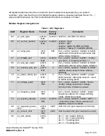
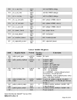
All register addresses must be converted to their hexadecimal equivalent by your system
controller. Also note that the Control Method register utilizes a hexadecimal data format “0x….”,
where 0x0000 indicates the Port Control Method is IDLE, as defined in Table 1.
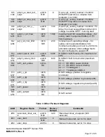
Modbus Register Assignments
Table 1: AC1 Registers
Addr
Register Name
Format
Factory
Default
Comments
64
p1_port_type
uint16x
R/W
0x0103 0x0103
– AC1 DELTA 3-Wire
65
p1_control_method
uint16x
R/W
0x0000 0x0000 - IDLE
0x0001 - NET
0x0402 - GRID POWER (GPWR)
0x0502
– FACILITY POWER (FPWR)
66
p1_ramp_rate
int16
R/W
500
If p1_control_method = 0x0402 or 0x502:
real power and reactive power ramp rate
while voltage-following
67
p1_throttle_port
int16x
R/W
0x0000 If p1_control_method = 0x0001: throttle
port DC3 = 0; throttle port DC2 = 1
68
p1_real_pwr_setpt
uint16
R/W
0
If p1_control_method = 0x0402 or 0x502:
real power setpoint while voltage-following
69
p1_reactive_pwr_set
pt
uint16
R/W
0
If p1_control_method = 0x0402 or 0x502:
reactive power setpoint while voltage-
following
70
p1_power_factor_set
pt
uint16
R/W
0
If p1_control_method = 0x0001: power
factor setpoint, otherwise unused
– need
to define scaling factor
71
p1_voltage_setpt
int16
RW
0
If p1_control_method = 0x502: line-to-
neutral voltage setpoint for voltage-
forming mode, otherwise unused
72
p1_frequency_setpt
int16
RW
0
If p1_control_method = 0x502: output
frequency setpoint for voltage-forming
mode, otherwise unused
74
p1_reactive_disable
int16x
RW
0x0000
If p1_control_method = 0x0001 (NET): 1
= automatic power factor correction is
disabled, defaut is enabled
89
p1_apparent_power_
limit
uint16
RW
3200
Soft VA Limit (port maximum is 32 kVA)
90
p1_current_limit
int16
RW
4400
Soft Current Limit (port maximum is 44 A)
96
p1_port_status
int16x
RO
b0 = 1: AC1 power limiting
b1 = 1: AC1 current limiting
b2 = 1: Throttling DC2
b3 = 1: Throttling DC3


