4
5
Installation of Ideal relay transceiver
1. Isolate power to boiler and heating system.
2. Remove the cover of the relay transceiver and screw the base to the wall,
directly above the existing system wiring if possible.
3. Disconnect and dispose of the wiring to the existing two channel timer and
room thermostat.
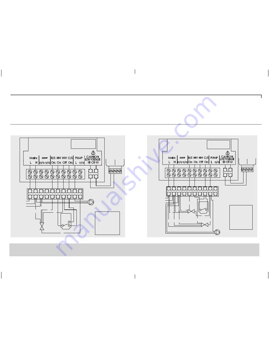
4. Make connections as in the diagrams below (except the opentherm wiring
- see next steps overleaf). Secure the wires in place using the cable clamps
provided.
If a frost thermostat is connected it should be from live to connection 8 (C/S On)
5. Power to the boiler and heating system should remain isolated.
Relay Transceiver
1
2
3
4
5
6
7
8
9
10
Opentherm
Boiler
opentherm
connector
Wiring
centre
(not
supplied)
L
N
E
R/S - Room Stat
HW - Hot Water
C/S - Cylinder Stat
bl
br
g/y
gr
or
w
KEY
- blue
- brown
- green/yellow
- grey
- orange
- white
Cylinder
Stat
1
C 2
Y plan
valve
or
bl
g/y
w
gr
Pump
(if external to boiler)
WEATHER
COMPENSATION
OPENTHERM
Opentherm
Pump
(if external to boiler)
Relay Transceiver
1
2
3
4
5
6
7
8
9
10
R/S - Room Stat
HW - Hot Water
C/S - Cylinder Stat
Cylinder
Stat
1 C
DHW
valve
CH
valve
g/y
bl
gr
or
or
br
bl
gr
g/y
br
wiring
centre
(not
supplied)
bl
br
g/y
gr
or
KEY
- blue
- brown
- green/yellow
- grey
- orange
Boiler
opentherm
connector
L
N
E
WEATHER
COMPENSATION
OPENTHERM
Ideal relay transceiver wiring (Y plan diagram)
Ideal relay transceiver wiring (S plan diagram)
*Where the Ideal Touch kit is being fitted to an existing installation (S or Y plan), the wire
connecting any SL IN on the boiler requires disconnecting and making safe. A link wire
should then be connected into the SL1 L-IN connection at the boiler†.
For further details refer to the boiler installation and sevicing instructions.
†Logic Heat H, Logic System S, Vogue Gen2 System


