


18
Classic
LXRS, RS
-
Propane Installation
SERVICING
SER
VICING
Heat Input / Setting Pressure
After each occasion of servicing, reference should be
made to Table 2, which quotes details of the rated output,
with the related burner setting pressure and the heat input.
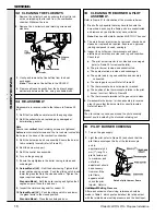
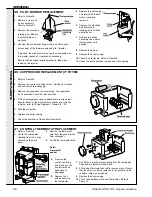
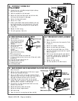
35 PILOT BURNER CHECKING
33 CLEANING THE BURNER & PILOT
ASSEMBLY.
Refer to Frame 31 for illustration of the procedure below.
1.
Brush off any deposits that may have fallen onto the
burner head, ensuring the flame ports are unobstructed,
and remove any debris that may have collected.
Note.
Brushes with metallic bristles MUST NOT be used.
2.
The main burner injector can be removed, checked and
cleaned or replaced as required. Ensure an approved
jointing compound is used, sparingly.
3.
Inspect the pilot burner, thermocouple and spark
electrode; ensure they are clear and in good condition.
Check that:
a.
The pilot burner injector is not blocked or damaged
(refer to Frame 39 for removal details).
b.
The pilot burner is clean and unobstructed.
c.
The spark electrode is clean and undamaged.
d.
The spark lead is in good condition and securely
connected.
e.
The spark gap is correct. Refer to Frame 35.
f.
The thermocouple tip is not burned or cracked.
g.
The position of the thermocouple relative to the pilot
burner is correct. Refer to Frame 35.
h.
The thermocouple terminal at the gas valve is clean.
4.
Re-assemble the burner / air box assembly in reverse
order. Ensure that the burner tab is correctly located.
Refer to Frame 31.
Note.
The pilot shield is positioned around the pilot assembly
bracket and is located by the electrode retaining nut.
Detail of pilot burner flame
1.
Turn on the gas supply.
2.
Light the pilot (refer to Frame 25) and check that the
pilot flame envelopes the tip of the thermocouple
and is
approximately 25
mm (1") long. The
pilot is factory set
to maximum and
no further
adjustment should
be necessary.
However, if the
pilot flame
appears small,
check the pilot
injector. Refer to
Frame 39.
Re-assemble in reverse order to that shown in Frames 30
to 33.
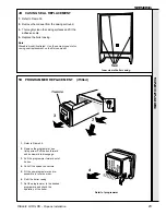
1.
Refit the flue baffles and retain with the spring clips.
2.
Refit the collector hood, replacing any damaged or
deteriorating gaskets.
Note.
Ensure rear
vertical
hood retaining screws are tightened
before
rear horizontal screws and the tie rods are located into
the holes in the base of the combustion chamber
3.
Refit the burner and air box assembly. Ensure the burner
tab is correctly located (refer to Frame 31).
4.
Refit the burner support.
5.
Refit the control box assembly.
6.
Turn on the gas supply.
7.
Ensure the sightglass in the boiler casing is clean and
undamaged .
8. Deluxe Model (LX)
- Refit the boiler casing. Tighten the 2
lower captive casing screws. Push the sliding catch in and
lower the glass fascia to the closed position. Tighten the
upper captive casing screw.
Standard Model
- Refit the boiler casing and tighten the 3
captive screws. Close the pod door.
9.
Inspect the visible casing seal for correct fit.
10. Deluxe Model (LX)
- Push the sliding catch in and lower
the glass fascia to the closed position.
Standard Model -
Close the controls pod door.
34 RE-ASSEMBLY
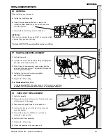
32 CLEANING THE FLUEWAYS
1.
Remove the collector hood by undoing the front tie rod
nuts and releasing the tie rods from the combustion
chamber. Withdraw the rods.
2.
Remove the 4 collector hood retaining screws and
washers.
3.
Unclip and remove the flue baffles from the heat
exchanger.
Note.
There are no flue baffles in the RS 255P.
4.
Remove all loose deposits from the heat exchanger,
particularly between the fins, using a suitable brush.


