


35
British Gas 440 - 480 RD2 -
Installation & Servicing
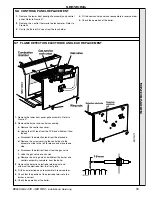
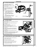
SERVICING
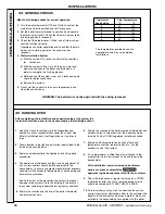
1. Remove the lower front panel and grille
assembly. Refer to Frame 47.
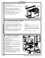
2. Remove the burner and controls assembly.
Refer to Frame 57.
3. Unscrew the gas inlet pipe from the valve.
4. Remove the 4 securing screws and
withdraw the valve from the burner
manifold.
5. Fit the new gas valve, ensuring that:
a. The valve is fitted the correct way round
- an arrow engraved on the valve
indicates the direction of flow.
b. The sealing 'O' ring supplied with the
valve is correctly fitted at the outlet
flange.
c. An approved jointing compound is used
when reconnecting the gas inlet pipe.
6. Reassemble in reverse order.
7. Check the operation of the boiler.
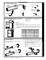
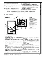
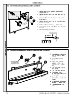
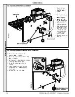
60 GAS VALVE REPLACEMENT
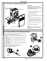
1. Remove the lower front panel, control panel and top panel.
Refer to Frame 47.
2. Remove the silicon rubber tube from the fan pressure
sensing point.
3. Disconnect the fan leads.
4. Remove the securing screw and withdraw the fan
thermistor sensor from the scroll.
5. Disconnect the silicon rubber tube from the top of the
collector hood.
6. Remove the 4 M4 screws on the top of the collector
hood and by sliding it forwards remove collector hood /
fan assembly.
7. Remove the three M4 screws retaining the fan to the
collector hood.
8. Fit the new fan and reassemble in reverse order. Lubricate
the fan 'O' ring with silicon grease. Ensure the fan leads, 2
sensing tubes and fan sensor are reconnected.
9. Check the operation of the boiler.
61 FAN REPLACEMENT
440FF & 450FF only
mex6052
2
2
4
Red
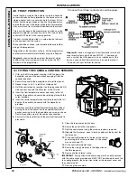
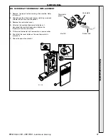
62 AIR PRESSURE SWITCH (APS) REPLACEMENT
1. Remove the lower front panel, control panel and the
top panel. Refer to Frame 47.
2. Remove the APS fixing screw.
3. Remove both sensing tubes from the APS.
4. Remove the 3 electrical connections from the APS.
5. Fit the new APS and reassemble in reverse order.
6. Check the operation of the boiler .
SER
VICING