background image

T002_H

!

LIGHTS OFF (-) BROWN - 01

PARKING LIGHTS (-) GRAY - 08

1

1

2

2

3

3

4

4

5

5

6

6

7

7

8

8

1

8

9

9

10

10

11

11

12

12

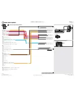
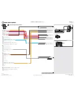
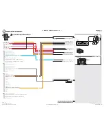
HEADLAMP SWITCH (B)

1: WHITE

VS1

VS2

M5

M4

MS1

MS2

JS1

VS6

VS5

JS2

JS3

1

1

VS3

VS4

02 WHITE/BLACK•BLUE DOT

06 WHITE•BLUE DOT

01 GRAY/BLACK•BLUE DOT

01 GRAY/BLACK•BLUE DOT

03 GRAY/RED•BLUE DOT

03 GRAY/RED•BLUE DOT
04 WHITE/RED•BLUE DOT

04 WHITE/RED•BLUE DOT
05 GRAY•BLUE DOT

05 GRAY•BLUE DOT

04 GREEN/WHITE•BLACK DOT

04 GREEN/WHITE•BLACK DOT

12 WHITE•BLACK DOT - PARKING LIGHTS (-) OUTPUT

12 WHITE•BLACK DOT - PARKING LIGHTS (-) OUTPUT

01 GREEN•BLACK DOT

01 GREEN•BLACK DOT
02 BLUE•BLACK DOT

02 BLUE•BLACK DOT
03 RED/WHITE•BLACK DOT

03 RED/WHITE•BLACK DOT

05 GREEN/BLACK•BLACK DOT

05 GREEN/BLACK•BLACK DOT
06 BLUE/WHITE•BLACK DOT - GWR (-) OUTPUT

06 BLUE/WHITE•BLACK DOT - GWR (-) OUTPUT
07 EMPTY

07 EMPTY
08 WHITE/PURPLE•BLACK DOT

08 WHITE/PURPLE•BLACK DOT
09 PURPLE/BLACK•BLACK DOT

09 PURPLE/BLACK•BLACK DOT

11 BROWN/BLACK•BLACK DOT

11 BROWN/BLACK•BLACK DOT

10 WHITE/BLACK•BLACK DOT - HORN (-) OUTPUT

10 WHITE/BLACK•BLACK DOT - HORN (-) OUTPUT

CUT LOOP FOR AUTOMATIC TRANSMISSION ONLY

CUT LOOP FOR AUTOMATIC TRANSMISSION ONLY

IGNITION SWITCH (A)

M2

M3

01 BROWN•SILVER DOT

01 BROWN•SILVER DOT
02 BLACK/WHITE•SILVER DOT

02 BLACK/WHITE•SILVER DOT
03 PURPLE•SILVER DOT

03 PURPLE•SILVER DOT
04 GREEN•SILVER DOT

04 GREEN•SILVER DOT
05 PURPLE/WHITE•SILVER DOT

05 PURPLE/WHITE•SILVER DOT
06 WHITE/BLUE•SILVER DOT

06 WHITE/BLUE•SILVER DOT

08 BLUE•SILVER DOT

08 BLUE•SILVER DOT
09 GRAY/BLACK•SILVER DOT

09 GRAY/BLACK•SILVER DOT
10 EMPTY

10 EMPTY

1: IMMOBILIZER CONNECTOR 7 PIN

2: IGNITION CONNECTOR 5 PIN

1: IMMOBILIZER HARNESS 7 PIN

07 GRAY•SILVER DOT - HOOD (-) INPUT

07 GRAY•SILVER DOT - HOOD (-) INPUT

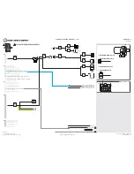
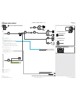
T-HARNESS / WIRING DIAGRAM - 1 OF 1

01

01
02

02
03

03
04

04
05

05
06

06
07

07
08

08
09

09
10

10
11

11
12

12
13

13
14

14
15

15
16

16
17

17
18

18
19

19
20

20

1

2

(NC)

(NC)
(NC)

(NC)
(NC)

(NC)

(NC)

(NC)

2: IGNITION HARNESS 5 PIN

HORN (-)

HOOD SWITCH

INSTALL THE SUPPLIED HOOD SWITCH IF THE VEHICLE IS NOT EQUIPPED WITH ONE.

(NC)

(NC)

(NC)

(NC)

RELAY

M1

01

01
02

02
03

03
04

04
05

05
06

06
07

07
08

08

!

M3

M1

M2

M5

M4

PAGE 3 OF 9

U.S. Patent No. 8,856,780

2015-2017 Honda Fit STD key AT 

www.idatalink.com

Automotive Data Solutions Inc. © 2016

ADS-RSA-HA6K-[HC2352AC]-EN

20161031

Содержание HC2352AC

Страница 1: ...mproper installation of this product be that either damage to the vehicle itself or to the installed device This device must be installed by a certiied technician Please review the Installation Guide...

Страница 2: ...firmware for your vehicle and that you carefully review the install guide 1 866 427 2999 support idatalink com idatalink com support www 12voltdata com forum www facebook com groups idatatech TABLE O...

Страница 3: ...WHITE BLACK DOT GWR OUTPUT 07 EMPTY 07 EMPTY 08 WHITE PURPLE BLACK DOT POC 1 2ND UNLOCK OTHER DOORS OUTPUT 08 WHITE PURPLE BLACK DOT POC 1 2ND UNLOCK OTHER DOORS OUTPUT 09 PURPLE BLACK BLACK DOT POC 2...

Страница 4: ...e the module s programming button OR if the remotes are already programmed to the vehicle press and hold the start button of the remote for 2 5 seconds Wait LED 2 will ash GREEN See the Module Diagnos...

Страница 5: ...a button then press and hold the antenna button The antenna s leds will turn solid BLUE Parking Light will ash once 1x Press once 1x on the LOCK button of each remote The antenna s leds will ash BLUE...

Страница 6: ...ional See RF kit user manual for alternate valet mode programming Time restriction Complete next step within 7 seconds Cycle ignition ON twice 2x OFF ON rapidly Press and release the BRAKE pedal three...

Страница 7: ...E TELEMATIC BLUE PORT For SmartStart use the module s RED Telematic port NC 10 11 12 13 14 15 16 1 2 3 4 5 6 7 8 9 MOBILE DEVICE PORT OBDII CONNECTOR 4 PIN BLACK CABLE MODULE WEBLINK PORT OBDII CONNEC...

Страница 8: ...U S Patent No 8 856 780 www idatalink com Automotive Data Solutions Inc 2016 HC2352AC PAGE 8 OF 12 20161024 TIBLE ACCESSORIES 2 OF 2 4 PIN BLACK CABLE MODULE RF PORT ANTENNA...

Страница 9: ...Set transmitter AUX buttons controls MENU 5 Programmable outputs POC Set actions for programmable outputs MENU 6 Pulse Timer Output Coniguration PTO Set duration for pulse timer outputs if used MENU...

Страница 10: ...5 RED ashes Tach set for VTS No tach programming required 6 RED ashes Tach set for assumed start No tach programming required III DURING REMOTE START Flashing RED Module incorrectly programmed Solid...

Страница 11: ...PARKING LIGHT FLASHES DIAGNOSTIC I WARNING The following applies only when the parking lights are connected and supported by the system 01 Engine tach signal is lost 02 Emergency brake is lost II If...

Страница 12: ...LACK 8 pin connector and the M4 BLACK 20 pin connector PRESS AND HOLD the module s programming button while connecting the M1 BLACK 8 pin connector and the M4 BLACK 20 pin connector Wait LED 1 will as...

Страница 13: ...015 HONDA ACCORD CROSSTOUR STD KEY AT www idatalink com Automotive Data Solutions Inc 2016 INSTALL GUIDE NOTICE The manufacturer will accept no responsability for any electrical damage resulting from...

Страница 14: ...HARDWIRE COMPONENT LOCATOR 1 OF 1 A B PAGE 2 OF 9 U S Patent No 8 856 780 2013 2015 Honda Accord Crosstour STD key AT www idatalink com Automotive Data Solutions Inc 2016 ADS RSA HA6K HC2352AC EN 201...

Страница 15: ...DOT HORN OUTPUT CUT LOOP FOR AUTOMATIC TRANSMISSION ONLY CUT LOOP FOR AUTOMATIC TRANSMISSION ONLY IGNITION SWITCH A M2 M3 01 BROWN SILVER DOT 01 BROWN SILVER DOT 02 BLACK WHITE SILVER DOT 02 BLACK WHI...

Страница 16: ...HARDWIRE COMPONENT LOCATOR 1 OF 1 A B PAGE 4 OF 9 U S Patent No 8 856 780 2013 2015 Honda Accord Crosstour STD key AT www idatalink com Automotive Data Solutions Inc 2016 ADS RSA HA6K HC2352AC EN 201...

Страница 17: ...ACK WHITE SILVER DOT 03 PURPLE SILVER DOT 03 PURPLE SILVER DOT 04 GREEN SILVER DOT 04 GREEN SILVER DOT 05 PURPLE WHITE SILVER DOT 05 PURPLE WHITE SILVER DOT 06 WHITE BLUE SILVER DOT 06 WHITE BLUE SILV...

Страница 18: ...with extended programming Connect power first Connect module to vehicle Set ignition to ON position Wait LED 1 will turn solid GREEN for 2 seconds Set ignition to OFF position Press UNLOCK on the OEM...

Страница 19: ...ch DO NOT PRESS BRAKE PEDAL Set ignition to ON position Wait 2 seconds for key validation Press and release BRAKE pedal Take over procedure completed Failure to follow procedure will result in vehicle...

Страница 20: ...problem persists 8 Press the START STOP button once 1x on the aftermarket keyfob to remote start vehicle Question 6 Does the vehicle remote start YES Go to next step NO Verify the remote programming...

Страница 21: ...in the wiring diagram Repeat the test and call technical support if the problem persists 6 Open hood 7 If not already installed afix the mandatory orange warning sticker under the hood and proceed to...

Страница 22: ...013 2017 HONDA ACCORD STD KEY AT www idatalink com Automotive Data Solutions Inc 2016 INSTALL GUIDE NOTICE The manufacturer will accept no responsability for any electrical damage resulting from impro...

Страница 23: ...001_H HARDWIRE COMPONENT LOCATOR 1 OF 1 A B PAGE 2 OF 9 U S Patent No 8 856 780 2013 2017 Honda Accord STD key AT www idatalink com Automotive Data Solutions Inc 2016 ADS RSA HA6K HC2352AC EN 20161031...

Страница 24: ...TION SWITCH A M2 M3 01 BROWN SILVER DOT 01 BROWN SILVER DOT 02 BLACK WHITE SILVER DOT 02 BLACK WHITE SILVER DOT 03 PURPLE SILVER DOT 03 PURPLE SILVER DOT 04 GREEN SILVER DOT 04 GREEN SILVER DOT 05 PUR...

Страница 25: ...001_W HARDWIRE COMPONENT LOCATOR 1 OF 1 A B PAGE 4 OF 9 U S Patent No 8 856 780 2013 2017 Honda Accord STD key AT www idatalink com Automotive Data Solutions Inc 2016 ADS RSA HA6K HC2352AC EN 20161031...

Страница 26: ...BLACK WHITE SILVER DOT 03 PURPLE SILVER DOT 03 PURPLE SILVER DOT 04 GREEN SILVER DOT 04 GREEN SILVER DOT 05 PURPLE WHITE SILVER DOT 05 PURPLE WHITE SILVER DOT 06 WHITE BLUE SILVER DOT 06 WHITE BLUE S...

Страница 27: ...ceed with extended programming Connect power first Connect module to vehicle Set ignition to ON position Wait LED 1 will turn solid GREEN for 2 seconds Set ignition to OFF position Press UNLOCK on the...

Страница 28: ...switch DO NOT PRESS BRAKE PEDAL Set ignition to ON position Wait 2 seconds for key validation Press and release BRAKE pedal Take over procedure completed Failure to follow procedure will result in ve...

Страница 29: ...f the problem persists 8 Press the START STOP button once 1x on the aftermarket keyfob to remote start vehicle Question 6 Does the vehicle remote start YES Go to next step NO Verify the remote program...

Страница 30: ...ated in the wiring diagram Repeat the test and call technical support if the problem persists 6 Open hood 7 If not already installed afix the mandatory orange warning sticker under the hood and procee...

Страница 31: ...2016 2017 HONDA CIVIC STD KEY AT www idatalink com Automotive Data Solutions Inc 2016 INSTALL GUIDE NOTICE The manufacturer will accept no responsability for any electrical damage resulting from impro...

Страница 32: ...T005_H HARDWIRE COMPONENT LOCATOR 1 OF 1 A B PAGE 2 OF 9 U S Patent No 8 856 780 2016 2017 Honda Civic STD key AT www idatalink com Automotive Data Solutions Inc 2016 ADS RSA HA6K HC2352AC EN 20161031...

Страница 33: ...BLACK DOT HORN OUTPUT CUT LOOP FOR AUTOMATIC TRANSMISSION ONLY CUT LOOP FOR AUTOMATIC TRANSMISSION ONLY IGNITION SWITCH A M2 M3 01 BROWN SILVER DOT 01 BROWN SILVER DOT 02 BLACK WHITE SILVER DOT 02 BLA...

Страница 34: ...T005_W HARDWIRE COMPONENT LOCATOR 1 OF 1 A B PAGE 4 OF 9 U S Patent No 8 856 780 2016 2017 Honda Civic STD key AT www idatalink com Automotive Data Solutions Inc 2016 ADS RSA HA6K HC2352AC EN 20161031...

Страница 35: ...2 BLACK WHITE SILVER DOT 03 PURPLE SILVER DOT 03 PURPLE SILVER DOT 04 GREEN SILVER DOT 04 GREEN SILVER DOT 05 PURPLE WHITE SILVER DOT 05 PURPLE WHITE SILVER DOT 06 WHITE BLUE SILVER DOT 06 WHITE BLUE...

Страница 36: ...oceed with extended programming Connect power first Connect module to vehicle Set ignition to ON position Wait LED 1 will turn solid GREEN for 2 seconds Set ignition to OFF position Press UNLOCK on th...

Страница 37: ...switch DO NOT PRESS BRAKE PEDAL Set ignition to ON position Wait 2 seconds for key validation Press and release BRAKE pedal Take over procedure completed Failure to follow procedure will result in ve...

Страница 38: ...if the problem persists 8 Press the START STOP button once 1x on the aftermarket keyfob to remote start vehicle Question 6 Does the vehicle remote start YES Go to next step NO Verify the remote progra...

Страница 39: ...ated in the wiring diagram Repeat the test and call technical support if the problem persists 6 Open hood 7 If not already installed afix the mandatory orange warning sticker under the hood and procee...

Страница 40: ...2015 2017 HONDA FIT STD KEY AT www idatalink com Automotive Data Solutions Inc 2016 INSTALL GUIDE NOTICE The manufacturer will accept no responsability for any electrical damage resulting from improp...

Страница 41: ...T002_H HARDWIRE COMPONENT LOCATOR 1 OF 1 A B PAGE 2 OF 9 U S Patent No 8 856 780 2015 2017 Honda Fit STD key AT www idatalink com Automotive Data Solutions Inc 2016 ADS RSA HA6K HC2352AC EN 20161031...

Страница 42: ...BLACK DOT HORN OUTPUT CUT LOOP FOR AUTOMATIC TRANSMISSION ONLY CUT LOOP FOR AUTOMATIC TRANSMISSION ONLY IGNITION SWITCH A M2 M3 01 BROWN SILVER DOT 01 BROWN SILVER DOT 02 BLACK WHITE SILVER DOT 02 BL...

Страница 43: ...T002_W HARDWIRE COMPONENT LOCATOR 1 OF 1 A B PAGE 4 OF 9 U S Patent No 8 856 780 2015 2017 Honda Fit STD key AT www idatalink com Automotive Data Solutions Inc 2016 ADS RSA HA6K HC2352AC EN 20161031...

Страница 44: ...02 BLACK WHITE SILVER DOT 03 PURPLE SILVER DOT 03 PURPLE SILVER DOT 04 GREEN SILVER DOT 04 GREEN SILVER DOT 05 PURPLE WHITE SILVER DOT 05 PURPLE WHITE SILVER DOT 06 WHITE BLUE SILVER DOT 06 WHITE BLUE...

Страница 45: ...roceed with extended programming Connect power first Connect module to vehicle Set ignition to ON position Wait LED 1 will turn solid GREEN for 2 seconds Set ignition to OFF position Press UNLOCK on t...

Страница 46: ...t switch DO NOT PRESS BRAKE PEDAL Set ignition to ON position Wait 2 seconds for key validation Press and release BRAKE pedal Take over procedure completed Failure to follow procedure will result in v...

Страница 47: ...if the problem persists 8 Press the START STOP button once 1x on the aftermarket keyfob to remote start vehicle Question 6 Does the vehicle remote start YES Go to next step NO Verify the remote progr...

Страница 48: ...rated in the wiring diagram Repeat the test and call technical support if the problem persists 6 Open hood 7 If not already installed afix the mandatory orange warning sticker under the hood and proce...

Страница 49: ...2016 2017 HONDA HR V STD KEY AT www idatalink com Automotive Data Solutions Inc 2016 INSTALL GUIDE NOTICE The manufacturer will accept no responsability for any electrical damage resulting from improp...

Страница 50: ...T003_H HARDWIRE COMPONENT LOCATOR 1 OF 1 A B PAGE 2 OF 9 U S Patent No 8 856 780 2016 2017 Honda HR V STD key AT www idatalink com Automotive Data Solutions Inc 2016 ADS RSA HA6K HC2352AC EN 20161031...

Страница 51: ...BLACK DOT HORN OUTPUT CUT LOOP FOR AUTOMATIC TRANSMISSION ONLY CUT LOOP FOR AUTOMATIC TRANSMISSION ONLY IGNITION SWITCH A M2 M3 01 BROWN SILVER DOT 01 BROWN SILVER DOT 02 BLACK WHITE SILVER DOT 02 BL...

Страница 52: ...T003_W HARDWIRE COMPONENT LOCATOR 1 OF 1 A B PAGE 4 OF 9 U S Patent No 8 856 780 2016 2017 Honda HR V STD key AT www idatalink com Automotive Data Solutions Inc 2016 ADS RSA HA6K HC2352AC EN 20161031...

Страница 53: ...02 BLACK WHITE SILVER DOT 03 PURPLE SILVER DOT 03 PURPLE SILVER DOT 04 GREEN SILVER DOT 04 GREEN SILVER DOT 05 PURPLE WHITE SILVER DOT 05 PURPLE WHITE SILVER DOT 06 WHITE BLUE SILVER DOT 06 WHITE BLUE...

Страница 54: ...oceed with extended programming Connect power first Connect module to vehicle Set ignition to ON position Wait LED 1 will turn solid GREEN for 2 seconds Set ignition to OFF position Press UNLOCK on th...

Страница 55: ...t switch DO NOT PRESS BRAKE PEDAL Set ignition to ON position Wait 2 seconds for key validation Press and release BRAKE pedal Take over procedure completed Failure to follow procedure will result in v...

Страница 56: ...if the problem persists 8 Press the START STOP button once 1x on the aftermarket keyfob to remote start vehicle Question 6 Does the vehicle remote start YES Go to next step NO Verify the remote progra...

Страница 57: ...rated in the wiring diagram Repeat the test and call technical support if the problem persists 6 Open hood 7 If not already installed afix the mandatory orange warning sticker under the hood and proce...

Отзывы: