


Thermal Imaging Integrated Network Camera
User Manual
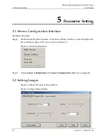
5 Parameter Setting
Issue V1.0 (2014-01-10)
23
Parameter
Description
Setting
image is displayed. After the FFC is complete,
the image is automatically recovered. Repeated
FFC operations can prevent the grainy and
image degradation problems. The FFC is
especially important when the temperature of
the camera changes. For example, after the
camera is powered on or the ambient
temperature
is
changed,
you
should
immediately perform the FFC.
Auto
: In the Automatic FFC mode, the camera
performs FFC whenever its temperature
changes by a specified amount or at the end of
a specified period of time (whichever comes
first). When this mode is selected, the FFC
interval (minutes) ranges from 5 to 30 minutes.
The temperature change of the camera is based
on the temperatures collected by the internal
temperature probe. The temperature of the
camera sharply changes when the camera is
powered on. The FFC is relatively frequent,
which is normal.
Manual
: In the manual FFC mode, the camera
does not automatically perform the FFC based
on the temperature change or the specified
period. You can press the Do FFC button to
select the manual FFC mode. When you feel
that the image is obviously degraded but the
automatic FFC is not performed, you can use
the manual FFC function to check whether the
image quality can be improved.
External:
In the external FFC mode, the
internal
mechanical
action
correction
mechanism is disabled. The uniform source
(black body) is placed in front of the camera.
This feature is useful if there are lens or lens
mount non uniformities that are not corrected
by an internal FFC. The camera will not
perform an FFC process on startup if the saved
state of the camera is External mode FFC.
Many customers have found that the palm of
their hand or a table is an adequate uniform
source to perform an External FCC.
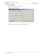
FFC
interval
(min)
In the automatic FFC mode, the FFC interval
ranges from 5 to 30 minutes.
[How to set]
Select
by
dragging
the
slider.
Содержание IV-THM42F25
Страница 2: ......


