


Innovative Circuit Technology Ltd.
9
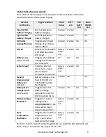
Status Indicators and Alarms
The 2 LEDs on the front panel and the Form-C alarm contacts on the back
indicate the status of the power supply:
Alarm or
Notification
Trigger Condition
LOAD
Output
BATT
LVD
Red
FAULT
LED
Green
POWER
LED
Input AC OK,
battery charging
Normal operation,
battery charging
Enabled
Enabled
-
ON
Input AC OK,
battery charged
Normal operation,
battery charged
Enabled
Enabled
-
ON
AC Under-
voltage Warning
Triggers when Input
Voltage drops below
approx. 90Vac
Enabled
Enabled
ON
ON
AC Fail
AC fails or front switch
is off (Battery above
LVD level)
Battery
power
only
Enabled
ON
-
Battery Low
(when AC Off)
Triggers when battery
voltage falls below the
LVD threshold
OFF
OFF
ON
-
System Fault
Indicates internal
circuit fault - Clears
when all fault
conditions are cleared.
Battery
power
only
Enabled
ON
-
Dead or
Disconnected
Battery
(AC
present)
Battery voltage is less
than 5/10/20V (on
12/24/48V models)
No charging
Enabled
OFF
-
ON
Battery Over
Voltage Fault
(AC present)
Triggers when the
battery voltage
exceeds the internal
OVP threshold for 3s
Enabled
OFF
ON
ON
DC Overvoltage
Shutdown
Triggers for output
voltage above
16.5/33/66VDC
for
1s.
Clears when Input
power cycled off/on
Battery
power
only
Enabled
ON
-
Over-
temperature
Shutdown
Triggers when internal
temperature is too
high. Clears when
back to normal range.
Battery
Power
only
Enabled
ON
-
The form-C alarm contact will be triggered for any condition that lights the red
FAULT LED, or shuts down the output of the unit.