background image

Installation Guide

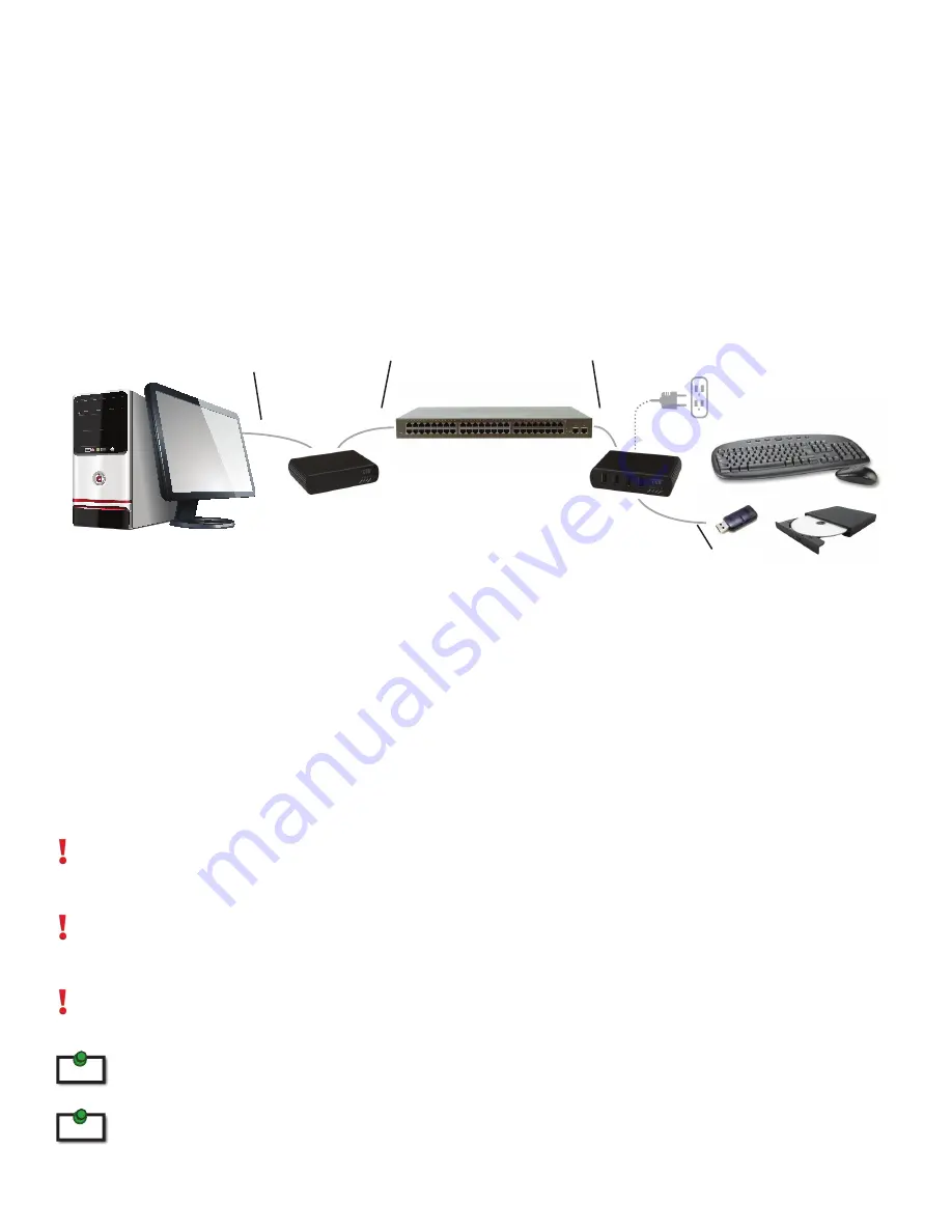
Installing the RG2304GE-LAN System on a Local Area Network

Requirements

To complete the installation, you will also require the following items that are not included with the product:

• 

USB compatible computer (host computer) with a USB compliant operating system

• 

USB compatible device(s)

• 

Two Cat 5e patch cables

• 

Preconfigured Local Area Network

Preparing your Network

Your network must be properly configured in order for full USB 2.0 throughput to be realized and for maxi-
mum stability and reliability of your devices.  Consult with your network administrator prior to installation.  
Using the RG2304GE-LAN over a network requires:

• 

Local Extender and Remote Extender to be on the same subnet

• 

RJ45 information outlets to be near the computer and USB devices to be connected to the network    

 switch(es)
• 

Pre-installed and configured Local Area Network


   USB 2.0 is capable of consuming up to 480Mbps.  The minimum requirement for using the RG2304-LAN is a Gigabit 

     (1000Base-T) network.  The performance of the USB network extension will be limited to the slowest link between the Local and 
      the Remote Extender.

     Some networks may be configured to block devices with unfamiliar MAC addresses.  If this is the case, you will need to provide 
     your network administrator the MAC addresses of the Local and Remote Extender units.  These can be found on the label on the 
     bottom of each unit.

     Some networks may be configured to block devices that consume a consistently high level of bandwidth.  The RG2304GE-LAN     
     may exhibit this behaviour when high bandwidth devices are connected.  Consult with your network administrator to resolve 
     this.

                 Units will be prepaired with each other if they were sold together in the same box.  If they are not paired, follow the 
                 instructions provided in the section for pairing a Local and Remote Extender.

                 Increasing the number of switches between the Local and Remote Extender may reduce the available bandwidth 
                 and as a result prevent some devices from functioning properly.

Local Extender

Computer

Gigabit Ethernet Switch(es)

Remote Extender

USB Devices

Up to 100m between extender and switch and between switches 

over Cat 5e (or better)

note

note

USB cable

USB cable or device 

connectors

Cat 5e Cable

Cat 5e Cable

6

Содержание USB 2.0 RG2304GE-LAN

Страница 1: ...USB 2 0 RG2304GE LAN 4 Port USB 2 0 Gigabit Ethernet LAN Extender System User Guide...

Страница 2: ...following two conditions 1 this device may not cause harmful interference and 2 this device must accept any interference received including interference that may cause undesired operation CE Statemen...

Страница 3: ...the Local Extender 7 Installing the Remote Extender 7 Installing the RG2304GE LAN System as Direct Connect 8 Requirements 8 Preparing Your Site 8 Installing the Local Extender 9 Connecting the Local...

Страница 4: ...ote Extender AC International Power Adapter Country Specific Power Cable Quick Start Guide Features The RG2304GE LAN incorporates ExtremeUSB technology enabling users to extend USB beyond the standard...

Страница 5: ...indicates the unit is attempting to establish a link 3 Host LED Green Indicates that the RG2304GE LAN system is properly enumerated on the host computer The LED blinks when the RG2304GE LAN is in a s...

Страница 6: ...is no link between Local and Remote Extenders Fast blinking indicates the unit is in Pairing mode slow blinking indicates the unit is attempting to establish a link 4 Host LED Green Indicates that the...

Страница 7: ...network extension will be limited to the slowest link between the Local and the Remote Extender Some networks may be configured to block devices with unfamiliar MAC addresses If this is the case you w...

Страница 8: ...er near the computer 2 Connect the supplied USB cable between the Local Extender host port and a USB port on the host computer 3 Connect a Cat 5e patch cable not provided into the information outlet n...

Страница 9: ...ter accordingly 3 If you are using surface cabling install the Cat 5e cabling as desired and terminate it with the appropriate RJ45 ends If you are using premise cabling ensure Cat 5e cabling is insta...

Страница 10: ...Premise Cabling 1 Connect a Cat 5e patch cable not provided into the information outlet near the host computer 2 Connect the patch cable into the Link port of the Local Extender 3 Connect a Cat 5e pat...

Страница 11: ...s controllers by clicking the sign If the RG2304GE LAN has been installed correctly you should find it listed as a Generic USB Hub To open Device Manager in Windows XP Right click My Computer then sel...

Страница 12: ...conds The Link LED will start flashing 3 Within 10 minutes of activating the pairing mode on the Local Extender press and hold the Pairing button on the back of the Remote Extender Release the button...

Страница 13: ...l and the Remote Extenders are off There is no connection between the Local and Remote Extenders 1 Ensure Cat 5e cable is connected between the Local and Remote Extenders Cat 5e or better cable UTP wi...

Страница 14: ...l Extender from the computer 3 Disconnect the Remote Extender from the AC power adapter 4 Reconnect the Local Extender to the computer 5 Reconnect the Remote Extender to the AC power adapter 6 In the...

Страница 15: ...the network cabling Cat 5e to the Local Extender unit and Remote Extender unit You may use either the T568A scheme Table 1 or the T568B scheme Table 2 for cable termination as the USB 2 0 RG2304GE LA...

Страница 16: ...x 1 0 Enclosure Material Black Anodized Aluminum REMOTE EXTENDER USB Connectors 4 x USB 2 0 Type A Receptacles Link Connector 1 x RJ45 Dimensions 100mm x 76mm x 26mm 3 9 x 3 0 x 1 0 Enclosure Materia...

Отзывы: