


SERVICE AND TECHNICAL SUPPORT MANUAL
Gas Furnace: N9MSB
Specifications subject to change without notice.
26
440 04 4412 01
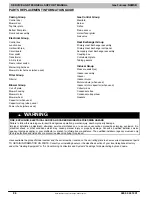
PARTS REPLACEMENT INFORMATION GUIDE
Casing Group
Control door
Blower door
Top filler plate
Bottom filler plate
Door knob assembly
Electrical Group
Control box
Junction box
Limit switch(es)
Circuit board
Door switch
Transformer
3
−
Amp fuse
Flame rollout switch
Main wiring harness
Blower motor harness (when used)
Filter Group
Filter(s)
Blower Group
Cut
−
off plate
Blower housing
Blower motor
Blower wheel
Capacitor (when used)
Capacitor strap (when used)
Power choke (where used)
Gas Control Group
Manifold
Burner
Orifice
Flame sensor
Hot surface igniter
Gas valve
Heat Exchanger Group
Primary Heat Exchanger assembly
Primary Heat Exchanger cell panel
Secondary Heat Exchanger assembly
Coupling box
Containment plate
Tubing gaskets
Inducer Group
Pressure switch(es)
Inducer assembly
Inducer
Inducer motor
Motor module (when used)
Inducer motor capacitor (when used)
Collector box
Condensate trap
Condensate trap elbow
Gaskets
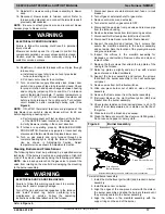
!
WARNING
FIRE, EXPLOSION, ELECTRICAL SHOCK AND CARBON MONOXIDE POISONING HAZARD
Failure to follow this warning could result in dangerous operation, personal injury, death or property damage.
Improper installation, adjustment, alteration, service, maintenance, or use can cause carbon monoxide poisoning, explosion, fire,
electrical shock, or other conditions which may cause personal injury or property damage. Consult a qualified installer, service
agency, local gas supplier, or your distributor or branch for information or assistance. The qualified installer or agency must use only
factory-authorized and listed kits or accessories when modifying this product.
Have available the product/model number and the serial number located on the unit rating plate to ensure correct replacement parts.
TO OBTAIN INFORMATION ON PARTS: Consult your installing dealer or the classified section of your local telephone directory
under the “Heating Equipment“ or “Air Conditioning Contractors and Systems” headings for dealer listing by brand name.


