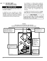
background image


3

SECTION 1 

INSTALLATION 


POUR VOTRE SÉCURITÉ 


NE PAS ENTREPOSER OU UTILISER D’ESSENCE, 
DE LIQUIDES OU DE VAPEURS INFLAMMABLES À 
PROXIMITÉ  DE CET APPAREIL OU DE TOUT 
AUTRE APPAREIL. 
 
NE PAS TENTER DE DÉMARRER LE BRÛLEUR SI 
UN EXCÉDENT DE MAZOUT S’EST ACCUMULÉ, SI 
L’APPAREIL DE CHAUFFAGE CENTRAL EST 
REMPLI DE VAPEUR OU SI LA CHAMBRE DE 
COMBUSTION EST TRÈS CHAUDE. 


1.1) 

DANGER, MISE EN GARDE ET 
AVERTISSEMENT 


Comprenez bien la portée des mots suivant : 

DANGER, MISE 

EN GARDE

 ou 

AVERTISSEMENT

. Ces mots sont associés 

aux symboles de sécurité. Vous les retrouverez dans le 
manuel de la façon suivante : 


DANGER 

Le mot 

DANGER

 indique les plus graves 

dangers, ceux qui 

provoqueront

 la mort ou des 

dommages corporels et/ou matériels sérieux.


MISE EN GARDE 


L’expression MISE EN GARDE signifie un 
danger qui peut entraîner la mort ou des 
dommages corporels et/ou matériels.  


AVERTISSEMENT 


Quant au mot 

AVERTISSEMENT

, il est utilisé 

pour indiquer les pratiques dangereuses qui 

peuvent 

provoquer des dommages corporels 

et/ou matériels mineurs. 


MISE EN GARDE 


N’utiliser qu’avec du mazout # 2 maximum.  Ne 
pas utiliser d’essence, d’huile à moteur ou toute 
autre huile contenant de l’essence. 


MISE EN GARDE 


Ne jamais faire brûler de déchets ou de papier 
dans le système de chauffage. Ne jamais laisser 
de chiffons ou de papier à proximité de l’unité. 


AVERTISSEMENT 

Ces instructions devraient être utilisées par des 
techniciens qualifiés et formés pour installer ce 
type d’appareils de chauffage central. 
L’installation de cet appareil par une personne 
non qualifiée peut endommager l’équipement 
et/ou conduire à des conditions hasardeuses 
susceptibles d’entraîner des dommages 
corporels. 


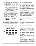
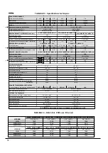
Tableau de correspondance des modèles 

Modèles 

AMP105-IE2 BMF-105  LBM105 
AMP120-IE2 BMF-125  LBM120 
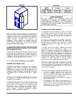


IMPORTANT:

 Pour l’installation de l’évacuateur mural 

du système de combustion scellé, référer au manuel 
d'installation du SCS-4. L’appareil doit être installé en 
position de débit ascendant lorsqu’il est utilisé avec un 
SCS. 


Содержание AMP105-IE2

Страница 1: ...ntr les Appeler un technicien qualifi Mod les AMP105 IE2 AMP120 IE2 BMF 105 BMF 125 LBM105 LBM120 2006 03 17 X40002 Rev L INSTALLATION MULTIPOSITION AVEC CHEMIN E INSTALLATION EN D BIT ASCENDANT AVEC...

Страница 2: ...ERTISSEMENT il est utilis pour indiquer les pratiques dangereuses qui peuvent provoquer des dommages corporels et ou mat riels mineurs MISE EN GARDE N utiliser qu avec du mazout 2 maximum Ne pas utili...

Страница 3: ...n raccordement un vent de dimensions ad quates La capacit d air de cet appareil de chauffage central est con ue pour permettre le refroidissement du d bit d air Se r f rer au tableau 4 pour conna tre...

Страница 4: ...T Ne pas obstruer les ouvertures d air de combustion de l appareil de chauffage central Toute obstruction r sultera en une combustion inad quate et accro t les risques d incendie et ou de dommages cor...

Страница 5: ...ble d installer des pales acoustiques rotatives ou d isoler les conduits tel que d crit au point b d Si une seule grille d air est utilis e les conduites entre la grille et l appareil de chauffage cen...

Страница 6: ...hemin e de ma onnerie Cet appareil de chauffage central peut tre vacu dans une chemin e de ma onnerie existante Toutefois l appareil de chauffage central ne doit pas tre vacu dans une chemin e vacuant...

Страница 7: ...unit et le r gulateur de tirage tel qu indiqu sur les instructions fournies avec le dispositif d arr t anti refoulement Le dispositif d arr t doit aussi faire l objet d un entretien annuel R f rer au...

Страница 8: ...refoulement Installation en d bit d air ascendant et vacuation verticale FIGURE4 Arrangement g n ral du syst me anti refoulement Installation en d bit d air ascendant et vacuation horizontale FIGURE...

Страница 9: ...e est fix e au tube d air du br leur et aucun ajustement n est requis pour la longueur d insertion AVERTISSEMENT Si le relais de combustion install sur le br leur est de la s rie R7184 de Honeywell NE...

Страница 10: ...tiliser TABLEAU 2 Fournaise Mod les Filtre air Dim Ouverture Dim AMP LBM et BMF 075 090 et 105 16 x 24 15 x 23 AMP LBM et BMF 120 140 et 155 18 x 30 17 x 29 1 3 11 Installation l horizontale ou d bit...

Страница 11: ...25 W C et 035 W C 4 Pour les installations avec vacuateur mural SCS la pression dans le tuyau d vacuation doit correspondre celle sp cifi e dans les tableaux de sp cifications techniques 5 La pression...

Страница 12: ...en fermant les registres de retour d air et laisser l appareil de chauffage central s teindre en limite lev e Le br leur va s teindre OFF et le ventilateur principal devrait continuer fonctionner Enle...

Страница 13: ...ecyclage voir section 2 9 3 et fera 3 essais de d marrage Le nombre d essais maximum est de 3 Apr s le contr le R7184 tombe en mode s curit lockout state 2 9 2 V rification de la pression et du vacuum...

Страница 14: ...appareil de chauffage central sans filtre air Les filtres jetables devraient tre remplac s au moins une fois par ann e Si l appareil de chauffage central est quip pour la climatisation les filtres dev...

Страница 15: ...AVERTISSEMENT Assurez vous que le ventilateur est ad quatement soutenu quand vous le sortez des rails surtout en position horizontale ou en d bit descendant afin d viter d chapper le ventilateur et d...

Страница 16: ...sse du technicien de service R SULTAT DU TEST DE MISE EN MARCHE Gicleur Pression lb po 2 Ajustements du br leur Bande principale Bande fine Position de la t te CO2 Indice de fum e Bacharach Temp ratur...

Страница 17: ...BE 3 3 8 D flecteur bas r gime NON Disque statique mod le 2 3 4 3383 Gicleur 100 PSIG pression pompe Delavan 0 60 70B 0 65 70B 0 75 70B 0 85 70W 1 00 70W Pression de la pompe PSIG 120 135 130 140 120...

Страница 18: ...ALE LA CONDUITEPREMIERS 6 PI 2 2 3 DESSOUS FOURNAISE PLANCHER COMBUSTIBLEAVEC BASE 0 0 0 HORIZONTALE OU SOUS LE TUYAU FUM E 4 4 4 VERTICALE AU DESSUS DU TUYAU FUM E 9 9 9 DEVANT FOURNAISE 8 8 24 C T D...

Страница 19: ...ALE LA CONDUITEPREMIERS 6 PI 2 2 3 DESSOUS FOURNAISE PLANCHER COMBUSTIBLEAVEC BASE 0 0 0 HORIZONTALE OU SOUS LE TUYAU FUM E 4 4 4 VERTICALE AU DESSUS DU TUYAU FUM E 9 9 9 DEVANT FOURNAISE 8 8 24 C T D...

Страница 20: ...FIGURE 12 1 Diagramme lectrique AMP LBM BMF 075 090 et 105 br leur Beckett 21...

Страница 21: ...FIGURE 12 2 Diagramme lectrique AMP LBM BMF 120 140 et 155 br leur Beckett 22...

Страница 22: ...FIGURE 12 3 Diagramme lectrique AMP LBM BMF 075 090 et 105 br leur Riello 23...

Страница 23: ...FIGURE 12 4 Diagramme lectrique AMP LBM BMF 120 140 et 155 br leur Riello 24...

Страница 24: ...FIGURE 12 5 Diagramme lectrique AMP LBM BMF 075 090 105 120 140 et 155 br leur Beckett et vacuateur SMH 25...

Страница 25: ...FIGURE 12 6 Diagramme lectrique AMP LBM BMF 075 090 105 120 140 et 155 br leur Riello et vacuateur SMH 26...

Страница 26: ...FIGURE 12 7 Diagramme lectrique AMP LBM BMF 075 090 et 105 br leur B SCS 27...

Страница 27: ...FIGURE 12 8 Diagramme lectrique AMP LBM BMF 120 140 et 155 br leur B SCS 28...

Страница 28: ...29 COMPOSANTES ET PI CES DE REMPLACEMENT...

Страница 29: ...LISTE DE PI CES Code de fabrication AMP LBM BMF 075 090 105 30 B50058A...

Страница 30: ...85 02 COMPREND PANNEAU ISOLATION ET DEFLECTEUR 25 ISOLATION PANNEAU DE COTE B01645 02 26 HAUTE LIMITE 195 30F R02R003 27 GARNITURE COUVERCLE DE TUYAU A FUMEE B01214 28 GARNITURE BRIDE FIXE BECKETT N04...

Страница 31: ...LISTE DE PI CES Code de fabrication AMP LBM BMF 120 140 155 32 50062A...

Страница 32: ...E B01875 02 COMPREND PANNEAU ISOLATION ET DEFLECTEUR 25 ISOLATION PANNEAU DE COTE B01800 02 26 HAUTE LIMITE 175 20F R02R005 27 GARNITURE COUVERCLE TUYAU DE FUMEE B00205 28 GARNITURE BRIDE FIXE BECKETT...

Страница 33: ...imentation d huile B02251 7B Isolation urethane bas 3 4 x 17 B01526 80 24 Pompe avec valve soleno de N01Z068 7C Isolation urethane haut 3 4 x 22 1 2 B01526 81 25 Harnais pour bobine N01Z069 8 D tecteu...

Страница 34: ...l a qualified service technician Models AMP105 IE2 AMP120 IE2 BMF 105 BMF 125 LBM105 LBM120 2006 03 17 X40002 Rev L MULTI POSITION INSTALLATIONS WITH CHIMNEY UPFLOW INSTALLATIONS WITH SEALED COMBUSTIO...

Страница 35: ...esult in death or serious bodily and or material damage CAUTION Hazards or unsafe practices which CAN result in minor bodily and or material damage WARNING For use with grade 2 Fuel Oil maximum Do not...

Страница 36: ...and connection to a properly sized vent The air handling capacity of this furnace is designed for cooling as well Refer to Table 4 for the expected airflow at various external static pressures 1 3 LOC...

Страница 37: ...to provide combustion air requirements In unconfined spaces in buildings of conventional frame brick or stone construction infiltration may be adequate to provide air for combustion ventilation and d...

Страница 38: ...ARNING The coil MUST be installed on the air discharge side of the furnace Under no circumstances should the airflow be such that cooled conditioned air is allowed to pass over the furnace heat exchan...

Страница 39: ...h the furnace must be used for the proper functioning Installation instruction are included with the control 1 3 5 BLOCKED VENT SHUT OFF BVSO FOR CHIMNEY VENTING WARNING It is imperative that this dev...

Страница 40: ...Blocked Vent Shut Off device wiring Installation Horizontal with vertical exhaust Blocked Vent Shut Off device wiring Installation Upflow with horizontal exhaust FIGURE 4 Blocked Vent Shut Off device...

Страница 41: ...ir tube and no adjustment is required for insertion length CAUTION NEVER use the interrupted ignition function if a Honeywell R7184 series combustion relay is installed on the burner Oil Connections C...

Страница 42: ...de panel or on the bottom of the furnace to accommodate the return air ductwork A sufficient clearance should be provided for air filter access Refer to Table 2 for filter rack flange dimensions for r...

Страница 43: ...the heat exchanger or the flue pipe Refer to the Technical Specifications in this manual for overfire pressure values A high pressure condition may be caused by excessive combustion air due to the air...

Страница 44: ...able 4 2 8 Constant Blower Switch This furnace is equipped with a constant low speed blower option Whenever the room thermostat is not calling for heating or cooling the blower will run on low speed i...

Страница 45: ...er than 0 8 W C there is an obstruction in the flue pipe If the vacuum reading is close to or greater than 0 8 W C there is an obstruction in the air inlet pipe 2 9 3 R7184 Control operation Three sec...

Страница 46: ...exchanger or flue pipe every year but it is advisable to have a qualified service technician check the unit before each heating season to determine whether cleaning or replacement of parts is necessar...

Страница 47: ...UTION Do not dent or scratch the surface of the thermal switch If the thermal switch is damaged replacement is required 6 Clear and remove any build up or obstruction inside the heat transfer tube 7 R...

Страница 48: ...y for w ire sizing Max w ire lenght ft Max fuse size Amps Control transformer External control pow er available Heating Cooling BLOWER DATA Blow er speed at 0 50 W C static pressure MED LOW MED HIGH H...

Страница 49: ...RM AIR DUCT WITHIN 6 ft OF FURNACE 2 2 3 BOTTOM FURNACE COMBUSTIBLEFLOOR WITH SUB BASE 0 0 0 HORIZONTALLY OR BELOW FLUEPIPE 4 4 4 VERTICALLY ABOVEFLUEPIPE 9 9 9 FRONT FURNACE 8 8 24 SIDES TOP FLUEPIPE...

Страница 50: ...M AIR DUCT WITHIN 6 ft OF FURNACE 2 2 3 BOTTOM FURNACE COMBUSTIBLEFLOOR WITH THESUB BASE 0 0 0 HORIZONTALLY OR BELOW FLUEPIPE 4 4 4 VERTICALLY ABOVEFLUEPIPE 9 9 9 FRONT FURNACE 8 8 24 SIDES TOP FLUEPI...

Страница 51: ...19 FIGURE 12 1 Wiring diagram AMP LBM BMF 075 090 105 Beckett burner...

Страница 52: ...20 FIGURE 12 2 Wiring diagram AMP LBM BMF 120 140 155 Beckett burner...

Страница 53: ...21 FIGURE 12 3 Wiring diagram AMP LBM BMF 075 090 105 Riello burner...

Страница 54: ...22 FIGURE 12 4 Wiring diagram AMP LBM BMF 120 140 155 Riello burner...

Страница 55: ...23 FIGURE 12 5 Wiring diagram AMP LBM BMF 075 090 105 120 140 155 Beckett burner and sidewall venter SMH...

Страница 56: ...FIGURE 12 6 Wiring diagram AMP LBM BMF 075 090 105 120 140 155 Riello burner and sidewall venter SMH 24...

Страница 57: ...FIGURE 12 7 Wiring diagram AMP LBM BMF 075 090 105 B SCS burner 25...

Страница 58: ...FIGURE 12 8 Wiring diagram AMP LBM BMF 120 140 155 B SCS burner 26...

Страница 59: ...27 COMPONENTS AND REPLACEMENT PARTS...

Страница 60: ...PARTS LIST Model AMP LBM BMF 075 090 105 28 B50058A...

Страница 61: ...H BECKETT N04Z026 29A BURNER ASSEMBLY B03091 01 29B BURNER RIELLO 40 F3 N01F011 30 HEXAGONAL NUT 3 8 16NC ZINC F07F011 31 CAPACITOR HOLDER B01024 32 CAPACITOR 5 MF L01I001 33 MOTOR SUPPORT ASSEMBLY 1...

Страница 62: ...PARTS LIST Model AMP LBM BMF 120 140 155 30 B50062A...

Страница 63: ...TION AND BAFFLE 25 INSULATION LEFT SIDE PANEL B01800 02 26 HIGH LIMIT 175 20F R02R005 27 GASKET SMOKE BOX COVER B00205 28 GASKET FIXED BREECH BECKETT N04Z026 29A BURNER ASSEMBLY B03092 01 29B BURNER R...

Страница 64: ...ine B02251 7B Urethane gasket 3 4 x 17 top B01526 80 24 Pump w ith solenoid valve N01Z068 7C Urethane gasket 3 4 x 22 1 2 bottom B01526 81 25 Wiring harness N01Z069 8 Pressure sw itch R99F022 26 Elect...

Отзывы: