background image

LCD-Kit03 640 x 480 / 18 bits
LTM10C209A

9

3

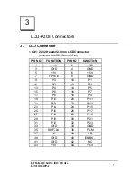
LCD-Kit03 Connectors

3.1    LCD Connector


CN1: 22x2 Header/2.0mm LCD Connector

           (connect to LCD Control Card)


PIN NO

FUNCTION

PIN NO

FUNCTION

1

+12V

2

+12V

3

GND

4

GND

5

+5V

6

+5V

7

FPVEE

8

GND

9

P0

10

P1

11

P2

12

P3

13

P4

14

P5

15

P6

16

P7

17

P8

18

P9

19

P10

20

P11

21

P12

22

P13

23

P14

24

P15

25

P16

26

P17

27

P18

28

P19

29

P20

30

P21

31

P22

32

P23

33

GND

34

GND

35

SHFCLK

36

FLM

37

M

38

LP

39

GND

40

ENBKL

41

GND

42

NC

43

+5V

44

+5V

Содержание LCD-Kit03

Страница 1: ... the part of the manufacturer In no event will the manufacturer be liable for direct indirect special incidental or consequential damages arising out of the use or inability to use the product or documentation even if advised of the possibility of such damages This document contains proprietary information protected by copyright All rights are reserved No part of this manual may be reproduced by a...

Страница 2: ......

Страница 3: ... LCD Kit03 Connection Layout 6 2 3 Unpacking Precautions 7 2 4 Backlight Inverter Control 8 3 LCD Kit03 Connectors 9 3 1 LCD Connector 9 3 2 Backlight Connector 10 3 3 Touch Panel Power Connector 11 3 4 Brightness Setting Connector 11 4 Voltage and BIOS Setting 12 4 1 BIOS Setting for SBCs with C T 65555 Chipset 13 4 2 BIOS Setting for SBCs with HM86508 Chipset 14 ...

Страница 4: ...D Kit03 is designed with High Luminance clear 256k colors and Low Reflection to present a High Image Quality With its thin and light weight plus compact size 10 4 LCD Kit03 is also the most suitable solution for FA OA Equipment Display Terminals Measuring Instrument and Industrial portable Workstation The LCD Kit03 comes with specifically designed mounting kit for fast installation It is also Plug...

Страница 5: ...ightness 250 cd m2 Pixel Format 1 pixel R G B dots Pixel Arrangement R G B Vertical Strip Pixel Pitch 0 33mm H x 0 33mm V Viewing Direction 6 o clock in direction of max contrast Viewing Angle 50o H 10o 30o V Contrast Ratio 100 1 Outline Dimensions 265 0mm W x 188 8mm H x 12 0mm D Surface Treatment Anti glare and Hard Coat 3H Backlight Twin cold cathode fluorescent lamps for sidelighting Operating...

Страница 6: ... following items one LTM10C209A 10 4 LCD Panel with its mounting kit one 70cm 44 pin LCD connection cable one BIOS Utility Diskette If any of these items is missing or damaged contact the dealer from whom you purchased the product Save the shipping materials and carton in case you want to ship or store the product in the future ...

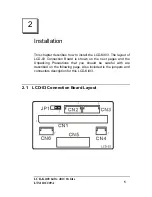
Страница 7: ...tall the LCD Kit03 The layout of LCD 03 Connection Board is shown on the next pages and the Unpacking Precautions that you should be careful with are described on the following page Also included is the jumpers and connectors description for this LCD Kit03 2 1 LCD 03 Connection Board Layout ...

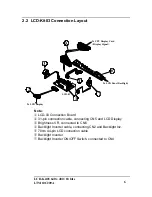
Страница 8: ...le connecting CN5 and LCD Display Brightness VR connected to CN6 Backlight Inverter cable connecting CN2 and Backlight Inv 70cm 44 pin LCD connection cable Backlight Inverter Backlight Inverter ON OFF Switch connected to CN4 To CPU Display Card Display Signal To LCD Panel Backlight To LCD Display LCD 03 1 2 3 5 6 4 LCD 03 7 ...

Страница 9: ...nnector or jumper while the power is on It will cause fatal damage to your LCD panel ü Make sure that every connector is connected in correct direction Any incorrect connection may cause smoke or burn of electrical parts or fatal damage of your LCD panel ü Be careful with the liquid crystal material Do not swallow inhale or have skin contact with this material in case that the LCD panel is broken ...

Страница 10: ...LCD Kit03 640 x 480 18 bits LTM10C209A 8 2 4 Backlight Inverter Control JP1 Backlight Inverter ON OFF control jumper PIN NO FUNCTION 1 2 USE FPVEE 2 3 USE ENBKL ...

Страница 11: ... Control Card PIN NO FUNCTION PIN NO FUNCTION 1 12V 2 12V 3 GND 4 GND 5 5V 6 5V 7 FPVEE 8 GND 9 P0 10 P1 11 P2 12 P3 13 P4 14 P5 15 P6 16 P7 17 P8 18 P9 19 P10 20 P11 21 P12 22 P13 23 P14 24 P15 25 P16 26 P17 27 P18 28 P19 29 P20 30 P21 31 P22 32 P23 33 GND 34 GND 35 SHFCLK 36 FLM 37 M 38 LP 39 GND 40 ENBKL 41 GND 42 NC 43 5V 44 5V ...

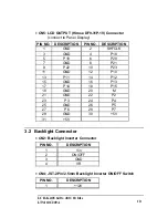
Страница 12: ...3 GND 4 P18 5 P19 6 P20 7 GND 8 P21 9 P22 10 P23 11 GND 12 P10 13 P11 14 P12 15 GND 16 P13 17 P14 18 P15 19 GND 20 M 21 GND 22 P2 23 P3 24 P4 25 GND 26 P5 27 P6 28 P7 29 GND 30 5V 31 5V 3 2 Backlight Connector CN2 Backlight Inverter Connector PIN NO DESCRIPTION 1 Vin 2 ON OFF 3 GND 4 VR CN4 JST 2Pin 2 5mm Backlight Inverter ON OFF Switch PIN NO DESCRIPTION 1 12V ...

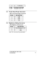
Страница 13: ... OFF Backlight Inverter OFF 3 3 Touch Panel Power Connector CN3 Touch Panel Power Connector PIN NO DESCRIPTION 1 12V 2 GND 3 GND 4 5V 3 4 Brightness Setting Connector CN6 Brightness VR Connector PIN NO DESCRIPTION 1 Series Resistor to VCC 2 VR 3 GND Note Pin1 is reserved for potentiometer ...

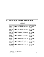
Страница 14: ...r Manual of your SBC or refer to the following tables BIOS Setting For SBCs with C T 65555 LCD CRT Interface Chipset the setting can be done simply in CMOS Setup For SBCs with HM86508 LCD CRT Interface Chipset the BIOS setting must be done by upgrading the VGA BIOS using the BIOS file in the attached disk Please refer to the following tables for more detail information Note To do the above setting...

Страница 15: ...pe 6 640x480 18Bit TFT Color JUKI 740E Peripheral Setup JP39 2 3 ON LCD CRT Selection Auto or Both LCD Type 6 640x480 18bit JUKI 745E Peripheral Setup JP39 2 3 ON LCD CRT Selection Auto or Both LCD Type 6 640x480 18bit NOVA 600 Peripheral Setup JP10 2 3 ON LCD CRT Selection Auto or Both LCD Type 6 640x480 18bit POS 566 Peripheral Setup JP23 2 3 ON LCD CRT Selection Auto or Both LCD Type 6 640x480 ...

Страница 16: ...t Setting ALi6117 5V only JUKI 750E use flash631j750lcd3 rom to upgrade to bios No volt Setting ACC Maple 5V only JUKI 752 use flash631j752lcd3 rom to upgrade bios No volt Setting ACC Maple 5V only PM 1021 use flash634 1021lcd3 rom to upgrade bios No volt Setting ALi6117 5V only NOVA 300 use flash634 n300lcd3 rom to upgrade bios No volt Setting ALi6117 5V only WAFER 4823 use flash631 4823lcd3 rom ...

Страница 17: ... the attached disk then type the bold letter command of the middle column then follow the instruction on your monitor Example for NOVA 300 SBC under DOS prompt type A flash634 n300lcd3 rom or C flash634 n300lcd3 rom if you have copied the files flash634 com and n300lcd3 rom to your hard disk ...

Отзывы: