WF-2572 Series
, Ethernet to Wi-Fi Bridge (V1.10, 2019/08/30) 20
4.3
Hardware Installation
The associated hardware configuration is shown as following steps.
Step1.
Checking the WF-2572 operation mode
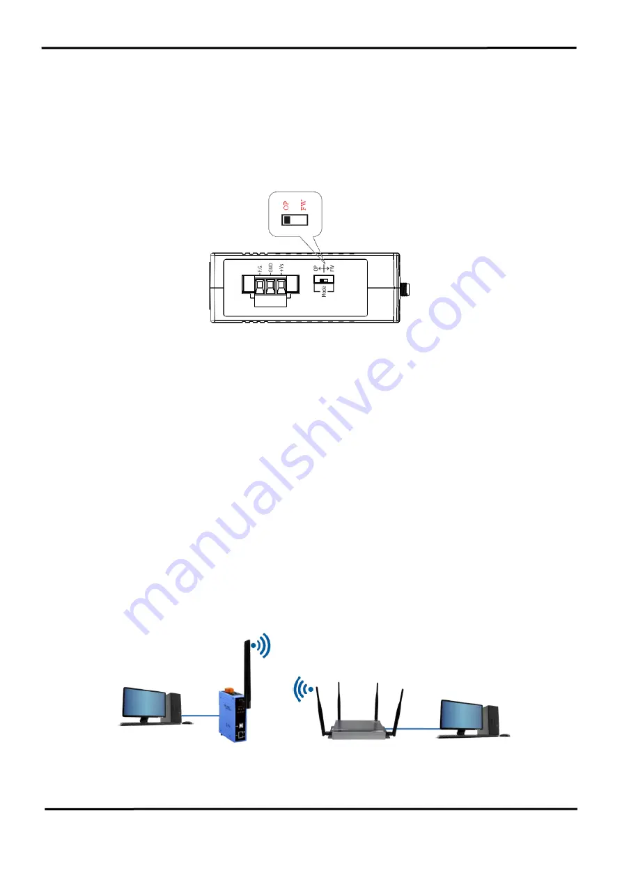
It needs to set the DIP switch to the "OP" position (operating mode). As resetting the
power, it will cause the device to operate in the operation mode.
Figure 4-3 “OP” Position
Step2.
Power connection
As shown in Figure 2-4, it needs to connect the power supply to power terminator of WF-
2572.
Step3.
USB port connection
WF-2572 supports USB communication for wireless configuration. If it does not need to
modify the parameter settings, this step can be omitted.
4.4
Infrastructure
Setting Description
4.4.1 Test Architecture
The test architecture shows in Figure 4-4. The WF-2572 connects to the PC by Ethernet
interface. The Wi-Fi AP connects to other PC by Ethernet interface. The WF-2572 set to
“Infrastructure” mode that it connects to the Wi-Fi AP.
Figure 4-4. Test Architecture of Infrastructure
Ethernet
WF-2572
(Infrastructure mode)
Wi-Fi AP
PC
IP:192.168.255.11
Ethernet
PC
IP:192.168.255.10


