High-speed Multifunction Boards
User Manual, Ver. 1.0, May 2021, PMH-033-10 Page 28
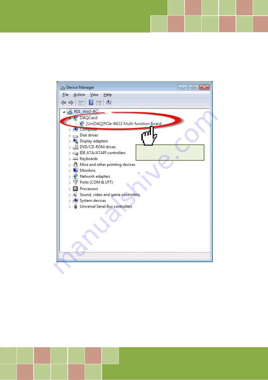
4.3.2
Check the Installation
Check that the PCIe-LM4 Series board is correctly listed in the Device Manager, as illustrated below.
Installation successful
Страница 1: ...rves the right to change this manual at any time without notice The information furnished by ICP DAS is believed to be accurate and reliable However no responsibility is assumed by ICP DAS for its use...
Страница 2: ...ding 13 2 4 4 Analog Input Data Acquisition Methods 14 2 5 PIN ASSIGNMENTS 15 2 5 1 CON1 2 Connector of the PCIe LM4 15 2 5 2 I O Connector Signal Descriptions 16 3 HARDWARE INSTALLATION 17 4 SOFTWARE...
Страница 3: ...High speed Multifunction Boards User Manual Ver 1 0 May 2021 PMH 033 10 Page 3 DN 68A 35 APPENDIX B REVISION HISTORY 36...
Страница 4: ...ckage should contain the following items One Analog Input board PCI AD64SU One printed Quick Start Guide Note If any of these items is missing or damaged contact the dealer from whom you purchased the...
Страница 5: ...g input channels It also has built in a 4k sample FIFO buffer for analog input data The PCI AD64SU also includes an onboard Card ID that enables the board to be recognized via software if two or more...
Страница 6: ...y the PCIe LM4 board Refer to Section 1 3 for more details Interface Universal PCI 3 3 V 5 V Interface Card ID switch Software Calibration Analog Input 64 Single ended 32 Differential Analog Input Cha...
Страница 7: ...Max Scan channel 250 kS s Max Over voltage Protection Continuous 35 Vp p Input Impedance 10 000 M 4pF Trigger Modes Software Pacer Data Transfer Polling Interrupt Accuracy 0 05 of FSR 1 LSB 25 C 10 V...
Страница 8: ...r Manual Ver 1 0 May 2021 PMH 033 10 Page 8 1 4 Applications Signal Analysis FFT and Frequency Analysis Transient Analysis Temperature Monitor Vibration Analysis Energy Management Other Industrial and...
Страница 9: ...2021 PMH 033 10 Page 9 2 Hardware Configuration 2 1 Board Layout The following is an overview of the board layout for each of the PCIe LM4 Series cards PCI AD64SU CON1 The Connector for Analog input...
Страница 10: ...d ID is 0x0 For more details regarding the SW1 Card ID settings refer to the table below NO 1 2 3 4 ID 0 ID 1 ID 2 ID 3 SW1 Default Settings Card ID Hex 1 ID0 2 ID1 3 ID2 4 ID3 0x0 ON ON ON ON 0x1 OFF...
Страница 11: ...High speed Multifunction Boards User Manual Ver 1 0 May 2021 PMH 033 10 Page 11 2 3 System Block Diagram The following is the block diagram for the PCIe LM4...
Страница 12: ...e input range User can individually program the input range of all channels on PCI A64SU board Input rage affects the resolution of the PCI A64SU for an AI channel Resolution refer to the voltage of o...
Страница 13: ...to measure differential type Analog Input signals for floating signal source AI CH 0 HI AI CH 0 LO AI CH n HI A GND AI CH n LO A GND 100 k 10 M 100 k 10 M PCIe LM4 Vs Floating Signal Source Floating S...
Страница 14: ...Trigger Mode Description Software Trigger No trigger signal is used and all A D operations are initiated by software After the clock signal is generated A D data will be recorded and saved to the buff...
Страница 15: ...High speed Multifunction Boards User Manual Ver 1 0 May 2021 PMH 033 10 Page 15 2 5 Pin Assignments 2 5 1 CON1 Connector of the PCI AD64SU...
Страница 16: ...ence Direction Description AI 0 31 AI 0 31 Input Analog Input channels 0 to 31 For Differential measurements for general purpose analog inputs AI 0 63 AGND Input Analog Input channels 0 to 63 For Sing...
Страница 17: ...dows 2000 or Windows XP etc Installing the driver first helps reduce the time required for installation and restarting the computer To install the PCIe LM4 Series cards follow the procedure described...
Страница 18: ...Boards User Manual Ver 1 0 May 2021 PMH 033 10 Page 18 Step 3 Shut down and switch off the power to the computer and then disconnect the power supply Step 4 Remove the cover from the computer Step 5...
Страница 19: ...Page 19 Step 6 Unscrew and remove the PCI slot cover from the computer case Step 7 Remove the connector cover from the I O board Step 8 Carefully insert the I O board into the PCI slot by gently pushi...
Страница 20: ...place using the retaining screw that was removed in Step 6 Step 10 Replace the covers on the computer Step 11 Re attach any cables insert the power cord and then switch on the power to the computer On...
Страница 21: ...can be found on the companion CD ROM or can be obtained from the ICP DAS FTP web site Install the appropriate driver for your operating system The location and website addresses for the installation...
Страница 22: ...ts screen verify that the DAQ Card is in the list of device and then click the Next button to continue Step 6 On the Select Additional Tasks screen click the Next button to continue Step 7 On the Down...
Страница 23: ...ter For detailed information about the hardware installation of the PCI AD64SU Series board refer to Chapter 3 Hardware Installation Step 2 Power on the computer and complete the Plug and Play install...
Страница 24: ...High speed Multifunction Boards User Manual Ver 1 0 May 2021 PMH 033 10 Page 24 Step 4 Click the Finish button Step 5 Windows pops up Found New Hardware dialog box again...
Страница 25: ...ating correctly The following is a description of how access the Device Manager in each of the major versions of Windows Refer to the appropriate description for the specific operating system to verif...
Страница 26: ...ager Windows 7 Step 1 Click the Start button and then click Control Panel Step 2 Click System and Maintenance and then click Device Manager Alternatively Step 1 Click the Start button Step 2 In the Se...
Страница 27: ...play the Start screen icon from the desktop view hover the mouse cursor over the bottom left corner of screen Step 2 Right click the Start screen icon and then click Device Manager Alternatively press...
Страница 28: ...function Boards User Manual Ver 1 0 May 2021 PMH 033 10 Page 28 4 3 2 Check the Installation Check that the PCIe LM4 Series board is correctly listed in the Device Manager as illustrated below Install...
Страница 29: ...se application of voltages in the field the procedure described below provides a method that allows the board installed in a specific system to be calibrated so that the correct voltages can be achiev...
Страница 30: ...ep by step description of the calibration process using the Windows Calibration Program for the PCI AD64SU which can be downloaded form https www icpdas com en product PCI AD64SU 5 2 1 PCIe LM4 Calibr...
Страница 31: ...V voltage source to PCI AD64SU CON1 AI0 Pin68 2 Connect GND source to PCI AD64SU CON1 AGND Pin60 3 Click Read button to get hexadecimal value Step 3 Calibrate the Analog Input Channel 0 to 0V 1 Connec...
Страница 32: ...V voltage source to PCI AD64SU CON1 AI0 Pin68 2 Connect GND source to PCI AD64SU CON1 AGND Pin60 3 Click Read button to get hexadecimal value Step 5 Calibrate the Analog Input Channel 0 to 0V 1 Connec...
Страница 33: ...N1 AI0 Pin68 2 Connect GND source to PCI AD64SU CON1 AGND Pin60 3 Click Read button to get hexadecimal value Step 7 Calibrate the Analog Input Channel 0 to 0V 1 Connect 0 V voltage source to PCI AD64S...
Страница 34: ...y 2021 PMH 033 10 Page 34 6 Windows API Function For more details regarding the Windows API Functions for the PCI AD64SU Series board refer to UniDAQ SDK User manual which can be downloaded from http...
Страница 35: ...mountable daughter board containing female 68 pin D sub I O Connectors and is designed to allow easy field wiring connections Pins 01 to 68 on the DN 68A daughter board are connected to the CON1 conn...
Страница 36: ...Manual Ver 1 0 May 2021 PMH 033 10 Page 36 Appendix B Revision history This chapter provides revision history information to this document The table below shows the revision history Revision Date Desc...