ICP DAS USA I-8092F Скачать руководство пользователя страница 70


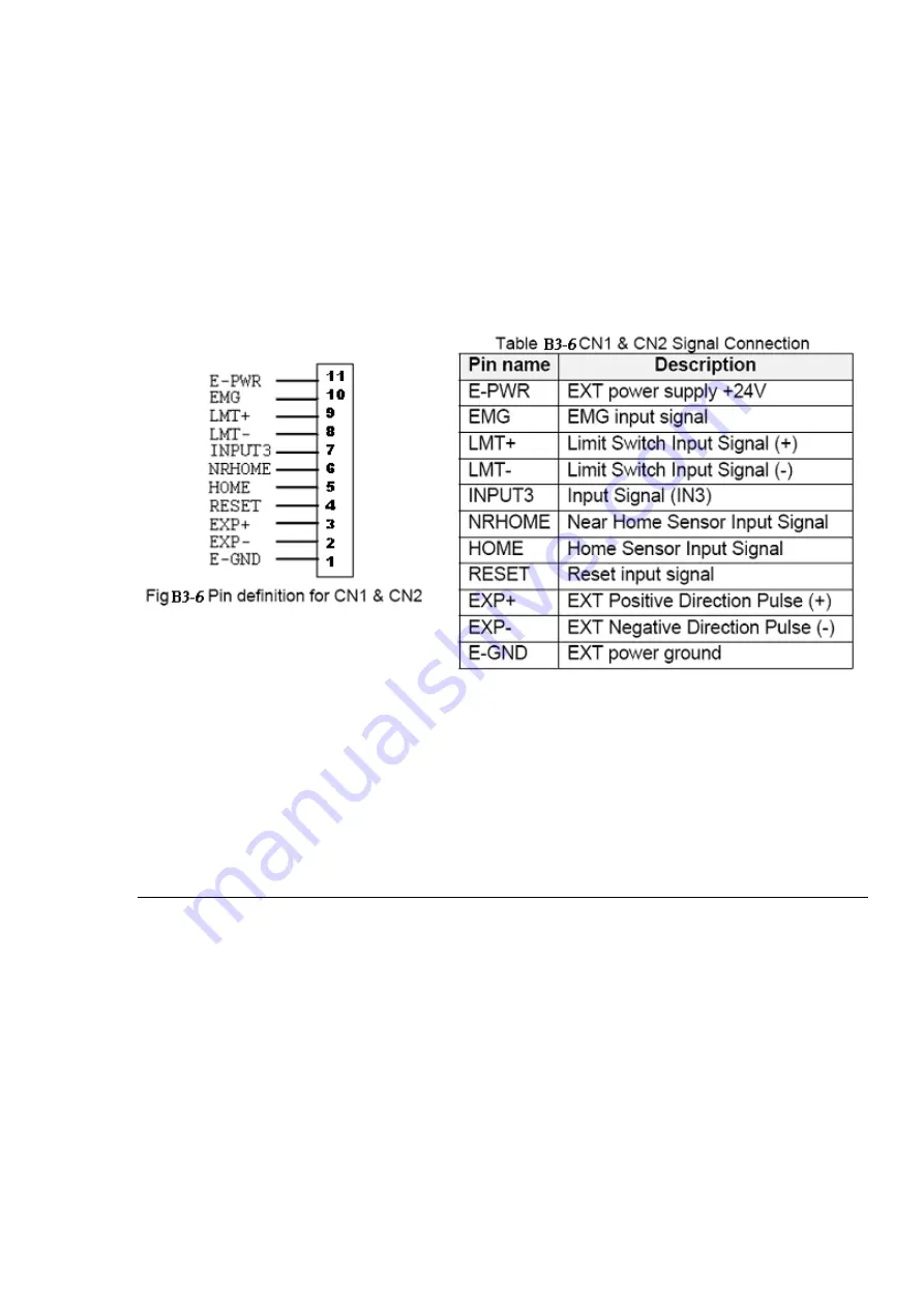
CN1& CN2 (The I/O signals of the X and Y axis) 

The connectors CN1 and CN2 are 11-pin connectors that enable you to connect to the 

signals of your motor drivers. Fig.B3-6 shows the pin assignment for the 20-pin connector 

on the DN-8237-PB, and the Table B3-6 shows its I/O connector signal description. 


RJ1 (The I/O signals of the FRnet)


The connectors RJ1 is an 8-pin RJ45 connector that enable you to connect to the signals 

of FRnet.    Fig.B3-7 shows the pin assignment for the 8-pin connector on the DN-8237-PB, 

and the Table B3-7 shows its I/O connector signal description.           

http:/www.icpdas.com                                   I8094Getting Started Manual for  WinPAC Ver.1.1 


70

Содержание I-8092F

Страница 1: ...I 8092F Getting Started Manual Version 1 0 Hardware Software Application Using I 8092F PAC Motion Control Module http www icpdas com I8092F Getting Started Manual for XPAC_CE 1...

Страница 2: ...ice The information furnished by ICPDAS Inc is believed to be accurate and reliable However no responsibility is assumed by ICPDAS Inc for its use or for any infringements of patents or other rights o...

Страница 3: ...Input Signal Filters 8 1 2 12 Software Limit 8 1 2 13 Manual Pulse Generator 8 1 2 14 LED for Module status 8 1 2 15 FRnet 8 1 3 Environment 9 1 4 Ordering Information 9 2 HARDWARE INSTALLATION 10 2...

Страница 4: ...olation Dialog 40 3 5 EzFRnet 42 3 6 Install Software Development Package 43 3 6 1 Installs SDK on WinPAC XPAC_CE 43 3 6 2 Installs SDK on XPAC_XPe 45 APPENDIX A OTHER TERMINAL BOARDS 46 A 1 DN 8237 D...

Страница 5: ...homing and others Besides it is a module that has full functions of I 8092F plus one port of FRnet The FRnet port allows this module to expand its fast remote I O easily This two wired FRnet can autom...

Страница 6: ...ation Interpolation range 8 388 607 8 388607 Vectors Speed of interpolation 1 PPS 4M PPS Bit interpolation Vectors Speed of interpolation 1 PPS 4M PPS Dependent on CPIU data writing time Relative inte...

Страница 7: ...ammable A B phase mode 1 1 2 and 1 4 A B phase Programmable direction of counter 1 2 5 Position counter Command counter range 2 147 483 648 2 147 483 647 Encoder counter range 2 147 483 648 2 147 483...

Страница 8: ...1 2 12 Software Limit There are two software limit for each axis SLimit SLimit Setting range 2 147 483 646 2 147 483 646 1 2 13 Manual Pulse Generator Fixed Pulse Driving Mode CW CCW pulse mode Conti...

Страница 9: ...92F 2 axis motion control module DN 8237GB For general purpose usage DN 8237DB For Delta ASDA Servo motor DN 8237MB For Mitsubishi J2 Servo motor DN 8237PB For Panasonic minas A4 Servo motor DN 8237YB...

Страница 10: ...ollers 2 1 2 Installation Prepare controller 1 Choose a PAC controller of ICPDAS WinPAC or XPAC_XPe XPAC_CE series and have empty slot 2 Turn power off Module Plug in controller and wiring 1 Plug in t...

Страница 11: ...Purpose Ampilifiers It has 2 axis I O signals 2 2 1 Board Layout for DN 8237 GB TB1 RJ1 CON3 CON2 CON1 37 PIN CONNECTOR EMG SW CON4 JP5 Y X DN 8237 MB 107mm 110mm JP1 JP2 JP3 JP4 Fig 2 1 Board layout...

Страница 12: ...CON1 The I O connector on the DN 8237 GB is a 37 pin connector that enables you to connect to the PISO PS200 or I 8092F motion card Fig 2 2 shows the pin assignment for the 37 pin I O connector on the...

Страница 13: ...M 30 Limit switch input signal for the Y axis X_STOP0 11 Stop 0 signal for the X axis Y_STOP0 29 Stop 0 signal for the Y axis X_STOP1 10 Stop 1 signal for the X axis Y_STOP1 28 Stop 1 signal for the Y...

Страница 14: ...ctors that enable you to connect to the I O signals for general purpose motor drivers Fig 2 3 shows the pin assignment for the 20 pin connector on the DN 8237 GB and the Table 2 3 shows its I O connec...

Страница 15: ...DN 8237 GB and the Table 2 4 shows its I O connector signal description TB1 The connector TB1 is 5 pin connector that enables you to connect to the signals of your motor drivers Fig 2 4 shows the pin...

Страница 16: ...ment for the 8 pin connector on the DN 8237 GB and the Table 3 5 shows its I O connector signal description 2 2 3 Jumper and Switch Settings JP5 Jumper 5 controls the EMG A signal of the CON4 connecto...

Страница 17: ...7 is the default setting to connect the EMG singals to GND The X EMG and Y EMG signal from CON4 not take effect If the switch is disconnected as shown in Fig 3 8 the emergency stop signals can be con...

Страница 18: ...indicated the type of pulse output signal for X axis However there are the same jumper settings for Y axis Jumper 3 4 for Y axis The following diagram is shown the selection condition of the jumper 1...

Страница 19: ...send the pulse train The CW and CCW signals can also be programmed as PULSE and DIR signals pait Two types of the pulse output signal Differential Type and Open Collector Type can be selected from JP2...

Страница 20: ...only at Pulse pins P P The driving direction is decided from the electric potential of Direction pins N N The following diagram is example signal of Pulse Direction pulse output mode Negative Command...

Страница 21: ...witch signal circuit 2 3 3 General Purpose Input Signals nINPOS nALARM INPOS is a digital input signal to indicate the In Position signal of the driver User can enable or disable the signal from the s...

Страница 22: ...re connected to motion IC Fig 2 13 Encoder signal connection 2 3 5 Emergency Stop Signal The following diagram is for Emergency STOP signal If the emergency signal is occurred the output pulse for all...

Страница 23: ...CCW mode continuous pulse CW CCW mode or A B phase manual pulsar mode by using the setting in section 3 5 Fig 2 15 EXP connection diagram 2 3 7 General Purpose Output signals Servo On Off The followin...

Страница 24: ...ng diagram is the connection example between MITSUBISH MR J2S AC servo driver and the extension boardDN 8237 Fig 2 17 The connection between MR J2S AC servo driver and DN 8237 extension board http www...

Страница 25: ...programming following chart is shown as follows The i 8092F software is divided into two parts Driver Libray Utilities for WinPAC XPAC_XPE XPAC_CE Application Programming Interafce API for Visual Stud...

Страница 26: ...he setup exe the files will be copied into the pre defined directories The samples for Visual Studio 2005 C wrapper file for Visual Studio 2005 C and module for Visual Studio 2005 Basic are provided t...

Страница 27: ...PAC_CE And the relevant utilities are installed into System_Disk i8092 The utilities are MotionCfg To configured the i8094 F and i8092F in XPAC_CE When XPAC_CE booting up the OS will refer to those co...

Страница 28: ...ftware package is installed one dialog will appear to make sure the re install when CAB updating Restart XPAC_CE the CAB updating will be successful http www icpdas com I8092F Getting Started ManualVe...

Страница 29: ...8092 Notice WinPAC supports addon driver after OS Ver 1 3 0 0 Please check the OS version of target WinPAC The utilities are MotionCfg To configured the i8094 F and i8092F in XPAC_CE When XPAC_CE boot...

Страница 30: ...d by some activated i 8094 F modules WinPAC will show the following message Please cancel the CAB installation remove i 8092F configurations with MotionCfg utility and excute Save and Reboot in WinPAC...

Страница 31: ...ore driver installing or system registry changing please disable EWF And enable the EWF after driver installing or registry changing Please refer to chapter 2 4 in xpac_8000_user_manual for detailed E...

Страница 32: ...8092F modules on backplane checks the relevant settings in system registries and the active motion modules Then MotionCfg combines these information and display the status of i 8094 F and i 8092F modu...

Страница 33: ...re booting In XPAC_XPe please disable EWF before excuting MotionCfg exe and enable EWF after changing the settings with MotionCfg exe Please restart the XPAC_XPe these setting changes will be activat...

Страница 34: ...hree categories of test function are displayed in the initial frame Configuration please refer to section 3 4 1 Basic Operation please refer to section 3 4 2 Interpolation Operation please refer to se...

Страница 35: ...arget Axis of the specific motion module 2 Encoder Mode Configures the encoder input mode as AB phase or CW CCW Up Down count Specify the frequency division at AB phase mode 1 1 AB Phase 1 2 AB Phase...

Страница 36: ...set_softlimit 6 Servo On Off Switch Related Function i8092_servo_on 7 Servo Input Signal Configurable feature enable disable and logical trigger level of the Servo Alarm signal Related Function i8092_...

Страница 37: ...tor 3 Position Counter Comp Counter Position counter is greater than or equal to the Positive comparator 4 Position Counter Comp Counter Position counter is less than the Positive comparator 5 End of...

Страница 38: ...pecific motion module 2 Parameter Setting The involved parameters are Start Velocity SV Driver Velocity V Acceleration A Deceleration D Jerk K Deceleration Rate L Output Pulse P and Offset Pulse AO 3...

Страница 39: ...and acceleration Related Function i8092_get_cmdcounter i8092_get_enccounter i8092_get_speed and i8092_get_acc 9 Limit Switch and Homing Signals Indicates the status of limit switches and home related...

Страница 40: ...s the target motion module 2 Interpolation Mode Setting Linear 2D and Circular interpolation Related Function i8092_t_line2_move i8092_s_line2_move and i8092_t_arc2_move 3 Acc Mode Setting Three accel...

Страница 41: ...Status Indicates the current Servo status On or Off 9 Finish Points Center Points Setting Configures the each Finish point of the interpolation related axes and the Center Points for circular interpol...

Страница 42: ...elect the Group Address for specific FRnet DI module Displays the DI status of target FRnet module Related Function i8092_get_FRnet_DI 3 RAn Digital Output Set Select the Group Address for specific FR...

Страница 43: ...amming Include The header file h wrapper file vc and modules vb for VS2005 programming Cpp VS2005 C Samples CSharp VS2005 C Samples Installed_Directory VS2005 VB VS2005 VB Samples For instance the ins...

Страница 44: ...http www icpdas com I8094Getting Started Manual for WinPAC Ver 1 1 44...

Страница 45: ...The related documentation Lib The Link file lib for eVC programming Include The header file h for eVC programming VC6 Samples VC6 samples Lib The Link file lib for VS2005 programming Include The heade...

Страница 46: ...r Delta ASDA A Series Ampilifier It has 2 axis I O signals A 1 1 Board Layout for DN 8237 DB TB1 RJ1 CN Y CN2 CN X CN1 CON1 37 PIN CONNECTOR EMG SW TB2 JP5 Y X DN 8237 DB 107mm 110mm JP2 JP1 Fig B1 1...

Страница 47: ...e I O connector on the DN 8237 DB is a 37 pin connector that enables you to connect to the PISO PS200 or I 8092F motion card Fig B1 2 shows the pin assignment for the 37 pin I O connector on the DN 82...

Страница 48: ...Limit switch input signal for the Y axis X_STOP0 11 Stop 0 signal for the X axis Y_STOP0 29 Stop 0 signal for the Y axis X_STOP1 10 Stop 1 signal for the X axis Y_STOP1 28 Stop 1 signal for the Y axis...

Страница 49: ...DB and the Table B1 3 shows its I O connector signal description TB2 The connector TB2 is 5 pin connector that enables you to connect to the signals of your motor drivers Fig B1 4 shows the pin assign...

Страница 50: ...rs that enable you to connect to the CN1 connector of Delta ASDA A series motor drivers Fig B1 5 shows the pin assignment for the 50 pin connector on the DN 8468 DB and the Table B1 5 shows its I O co...

Страница 51: ...n the DN 8237 DB and the Table B1 6 shows its I O connector signal description RJ1 The I O signals of the FRnet The connectors RJ1 is an 8 pin RJ45 connector that enable you to connect to the signals...

Страница 52: ...gs JP5 Jumper 5 controls the EMG A signal of the TB1 connector The following diagram is shown the selection condition of the jumper 5 Fig B1 8 Jumper 5 setting http www icpdas com I8094Getting Started...

Страница 53: ...s the default setting to connect the EMG singals to GND The EMG signals from CN1 and CN2 will not take effect If the switch is disconnected as shown in Fig B1 10 the emergency stop signals can be cont...

Страница 54: ...can select the reset function in CN1 and CN2 for each axis The following diagram is shown the selection condition of the JP1 Fig B1 15 JP 1 and 2 setting http www icpdas com I8094Getting Started Manu...

Страница 55: ...es Ampilifier It has 2 axis I O signals A 2 1 Board Layout for DN 8237 MB TB1 RJ1 CN YA CN YB CN2 CN XA CN XB CN1 CON1 37 PIN CONNECTOR EMG SW TB2 JP5 Y X DN 8237 MB 107mm 110mm Fig B2 1 Board layout...

Страница 56: ...e I O connector on the DN 8237 MB is a 37 pin connector that enables you to connect to the PISO PS200 or I 8092F motion card Fig B2 2 shows the pin assignment for the 37 pin I O connector on the DN 82...

Страница 57: ...Limit switch input signal for the Y axis X_STOP0 11 Stop 0 signal for the X axis Y_STOP0 29 Stop 0 signal for the Y axis X_STOP1 10 Stop 1 signal for the X axis Y_STOP1 28 Stop 1 signal for the Y axis...

Страница 58: ...3 shows its I O connector signal description Table B2 3 TB2 Signal Connection Name Number Description FR A 7 FRnet port A FR B 6 FRnet port B XOUT0 5 General output 0 for X axis YOUT0 4 General output...

Страница 59: ...r on the DN 8237 MB and the Table B2 4 shows its I O connector signal description Table B2 4 TB1 Signal Connection Name Number Description EXT_PWR 1 EXT POWER 24V EXT_PWR 2 EXT POWER 24V EXT_GND 3 EXT...

Страница 60: ...T POWER Ground N 2 Negative Direction Pulse P 3 Positive Direction Pulse NC 4 No connection Z 5 Encoder Z phase A 6 Encoder A phase B 7 Encoder B phase ERC 8 Error Count Clear EXT_PWR 9 EXT POWER 24V...

Страница 61: ...tion EXT_GND 1 EXT POWER Ground NC 2 No connection NC 3 No connection NC 4 No connection SVON 5 Servo On NC 6 No connection NC 7 No connection NC 8 No connection NC 9 No connection EXT_GND 10 EXT POWE...

Страница 62: ...Number Description ERC 12 Error Count Clear EXT_PWR 11 EXT POWER 24V EMG 10 Emergent Stop LMT 9 Limit switch Input Signal LMT 8 Limit switch Input Signal INPUT3 7 Input Signal IN3 NRHOME 6 Near HOME...

Страница 63: ...for the 8 pin connector on the DN 8237 MB and the Table B2 8 shows its I O connector signal description A2 3 Jumper and Switch Settings JP5 Jumper 5 controls the EMG A signal of the TB1 connector The...

Страница 64: ...s the default setting to connect the EMG singals to GND The EMG signals from CN1 and CN2 will not take effect If the switch is disconnected as shown in Fig B2 11 the emergency stop signals can be cont...

Страница 65: ...4 Series Ampilifier It has 2 axis I O signals A 3 1 Board Layout for DN 8237 PB TB1 RJ1 CN Y CN2 CN X CN1 CON1 37 PIN CONNECTOR EMG SW TB2 JP5 Y X DN 8237 PB 107mm 110mm Fig B3 1 Board layout for the...

Страница 66: ...e I O connector on the DN 8237 PB is a 37 pin connector that enables you to connect to the PISO PS200 or I 8092F motion card Fig B3 2 shows the pin assignment for the 37 pin I O connector on the DN 82...

Страница 67: ...Limit switch input signal for the Y axis X_STOP0 11 Stop 0 signal for the X axis Y_STOP0 29 Stop 0 signal for the Y axis X_STOP1 10 Stop 1 signal for the X axis Y_STOP1 28 Stop 1 signal for the Y axis...

Страница 68: ...PB and the Table B3 3 shows its I O connector signal description TB2 The connector TB2 is 5 pin connector that enables you to connect to the signals of your motor drivers Fig B3 4 shows the pin assign...

Страница 69: ...nectors that enable you to connect to the CN X5 connector of Panasonic motor drivers Fig B3 5 shows the pin assignment for the 50 pin connector on the DN 8468 PB and the Table B3 5 shows its I O conne...

Страница 70: ...n the DN 8237 PB and the Table B3 6 shows its I O connector signal description RJ1 The I O signals of the FRnet The connectors RJ1 is an 8 pin RJ45 connector that enable you to connect to the signals...

Страница 71: ...gs JP5 Jumper 5 controls the EMG A signal of the TB1 connector The following diagram is shown the selection condition of the jumper 5 Fig B3 8 Jumper 5 setting http www icpdas com I8094Getting Started...

Страница 72: ...Fig B3 9 is the default setting to connect the EMG singals to GND The EMG signals from CN1 and CN2 will not take effect If the switch is disconnected as shown in Fig B3 10 the emergency stop signals c...

Страница 73: ...Series Ampilifier It has 2 axis I O signals A 4 1 Board Layout for DN 8237 YB TB1 RJ1 CN Y CN2 CN X CN1 CON1 37 PIN CONNECTOR EMG SW TB2 JP5 Y X DN 8237 YB 107mm 110mm Fig B4 1 Board layout for the DN...

Страница 74: ...e I O connector on the DN 8237 YB is a 37 pin connector that enables you to connect to the PISO PS200 or I 8092F motion card Fig B4 2 shows the pin assignment for the 37 pin I O connector on the DN 82...

Страница 75: ...Limit switch input signal for the Y axis X_STOP0 11 Stop 0 signal for the X axis Y_STOP0 29 Stop 0 signal for the Y axis X_STOP1 10 Stop 1 signal for the X axis Y_STOP1 28 Stop 1 signal for the Y axis...

Страница 76: ...YB and the Table B4 3 shows its I O connector signal description TB2 The connector TB2 is 5 pin connector that enables you to connect to the signals of your motor drivers Fig B4 4 shows the pin assign...

Страница 77: ...nnectors that enable you to connect to the CN1 connector of Yaskawa motor drivers Fig B4 5 shows the pin assignment for the 50 pin connector on the DN 8468 YB and the Table B4 5 shows its I O connecto...

Страница 78: ...n the DN 8237 YB and the Table B4 6 shows its I O connector signal description RJ1 The I O signals of the FRnet The connectors RJ1 is an 8 pin RJ45 connector that enable you to connect to the signals...

Страница 79: ...gs JP5 Jumper 5 controls the EMG A signal of the TB1 connector The following diagram is shown the selection condition of the jumper 5 Fig B4 8 Jumper 5 setting http www icpdas com I8094Getting Started...

Страница 80: ...s the default setting to connect the EMG singals to GND The EMG signals from CN1 and CN2 will not take effect If the switch is disconnected as shown in Fig B4 10 the emergency stop signals can be cont...

Отзывы: