background image


PPC-150T-APL User’s Manual     

  IUMPPC150TAPL-01 Ver.1.0A    Jun, 2019                                   

18 


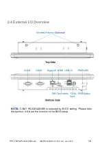
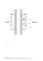
2.4 External I/O Overview 


NOTE: 

COM1  RS232/422/485  is  selected  by  BIOS  setting.  Please  refer 

the section, 4.6 to set the function in the BIOS setup. 


Содержание PPC-150T-APL Series

Страница 1: ...Ver 1 0A Jun 2019 i User s Manual PPC 150T APL Intel Apollo Lake Processor Compact Panel PC with 15 Resistive Touch Screen PPC 150T APL N4 4G PPC 150T APL N4 8G PPC 150T APL N3 4G Build to order PPC...

Страница 2: ...PPC 150T APL User s Manual IUMPPC150TAPL 01 Ver 1 0A Jun 2019 i REVISION DATE VERSION DESCRIPTION 2019 6 28 Version 1 0A New Release...

Страница 3: ...2019 ICOP Technology Inc Manual IUMPPC150TAPL 01 Ver 1 0A Jun 2019 TRADEMARKS ACKNOWLEDGMENT Intel Apollo Lake is the registered trademark of Intel Corporation Other brand names or product names appea...

Страница 4: ...e please turn off power before inserting or removing Do not open the cabinet to avoid electrical shock Refer to your nearest dealer for qualified personnel servicing Never touch un insulated terminals...

Страница 5: ...al I O Overview 18 2 5 External I O Pin Assignment 20 Ch 3 Hardware Installation 22 3 1 Installing the M 2 2242 SATA 23 3 2 Installing the 2 5 SATA HDD SDD 26 3 3 Installing the Mini PCIe Module 29 3...

Страница 6: ...IUMPPC150TAPL 01 Ver 1 0A Jun 2019 1 Ch 1 General Information 1 1 Product Description 1 2 Product Specifications 1 3 Inspection standard for TFT LCD Panel 1 4 Product Dimensions 1 5 Mounting Instructi...

Страница 7: ...design is perfect for the present demanding embedded and productive applications The new PPC 150T APL inherited PPC series smooth appearance and ultra texture aluminum exterior design to make your ind...

Страница 8: ...splay LAN Integrated 10 100 1000Mbps Ethernet x 1 Audio HD Audio Realtek ALC662VD CODEC Internal Drives 2 5 SATA HDD SSD Support SATA III 6 0Gb s M 2 Slot Support M Key SATA Interface 2242 I O HDMI x...

Страница 9: ...S Display Type 15 XGA TFT LCD Backlight Unit LED Display Resolution 1024 W x 768 H Brightness cd m2 250 nits Contrast Ratio 600 1 Display Color 262 144 Pixel Pitch mm 0 297 H x 0 297 V Viewing Angle V...

Страница 10: ...slight visible through 6 ND filter ELECTRICA L DEFECT BRIGHT DOT A Grade B Grade C Area O Area Total C Area O Area Total Note3 N 0 N 2 N 2 N 2 N 3 N 5 Note2 DARK DOT N 2 N 3 N 3 N 3 N 5 N 8 TOTAL DOT...

Страница 11: ...2019 6 Note 1 W Width mm L Length mm N Number Average Diameter a White Black Spot b Polarizer Bubble Note 2 Bright dot is defined through 6 transmission ND Filter as following Note 3 Display area C A...

Страница 12: ...A B C and D status adjacent defect dots including bright and dark adjacent dot And they will be counted 2 defect dots in total quantity The defects that are not defined above and considered to be prob...

Страница 13: ...PPC 150T APL User s Manual IUMPPC150TAPL 01 Ver 1 0A Jun 2019 8 1 4 Product Dimensions...

Страница 14: ...rt VESA Mount that is an optional for ordering Please contact your region sales for ordering Ordering part number VESA MT PPC APL SET 1 Place VESA bracket and VESA MT PPC APL SET together 2 Lock 4 scr...

Страница 15: ...of mounting wall thickness limitation is 20 mm 2 PANEL MT PPC APL SET includes 6pcs of clamp and screw and each clamp and screw is paired Screws 6pcs of clamp and screw together respectively 3 Place...

Страница 16: ...ive touch screen 150T 15 LCD with Resistive touch screen 150P 15 LCD with PCAP touch screen 3 CPU Type Code 8 9 N4 Intel Apollo Lake N4200 Standard Quad Core 6W N3 Intel Apollo Lake N3350 Optional Dua...

Страница 17: ...12V Power Input PPC 150T APL N3 4G BTO 15 Panel PC w Intel Apollo Lake N3350 4GB DRAM 3U Giga LAN 2S Touch DC12V Power Input PPC 150T APL N3 8G BTO 15 Panel PC w Intel Apollo Lake N3350 8GB DRAM 3U Gi...

Страница 18: ...L User s Manual IUMPPC150TAPL 01 Ver 1 0A Jun 2019 13 Ch 2 System Installation 2 1 CPU Board Outline 2 2 Connector Summary 2 3 Connector Pin Assignments 2 4 External I O Overview 2 5 External I O Pin...

Страница 19: ...PPC 150T APL User s Manual IUMPPC150TAPL 01 Ver 1 0A Jun 2019 14 2 1 CPU Board Outline PPC APL CPU Board...

Страница 20: ...M 2 SATA Connector 75 pin J7 COM1 RS232 422 485 2 0mm 9 pin pin header 9 pin J8 COM2 RS232 2 0mm 9 pin pin header 9 pin J9 Mini PCIe External Mini PCIe Connector 52 pin J10 Front Panel Header 2 0mm 9...

Страница 21: ...D2 4 RTS2 5 TXD2 6 CTS2 7 DTR2 8 RI2 9 GND Pin Signal Name Pin Signal Name 1 HDDLED 2 PWRLED 3 HDDLED 4 PWRLED 5 GND 6 PWRBT 7 RSTSW 8 GND 9 VCC Pin Signal Name Pin Signal Name 1 VCC 2 VCC 3 USB2_D1 4...

Страница 22: ...al Name Pin Signal Name 1 MIC_L 2 AUDIO_GND 3 MIC_R 4 AUDIO_JD 5 LINEOUT2_R 6 MIC_JD 7 SENSE_FB 9 LINEOUT2_L 10 LINE2_JD Pin Signal Name Pin Signal Name 1 GPIO80 2 GPIO81 3 GPIO82 4 GPIO83 5 GPIO84 6...

Страница 23: ...50T APL User s Manual IUMPPC150TAPL 01 Ver 1 0A Jun 2019 18 2 4 External I O Overview NOTE COM1 RS232 422 485 is selected by BIOS setting Please refer the section 4 6 to set the function in the BIOS s...

Страница 24: ...PPC 150T APL User s Manual IUMPPC150TAPL 01 Ver 1 0A Jun 2019 19...

Страница 25: ...XD2 4 DTR2 5 GND 6 DSR2 7 RTS2 8 CTS2 9 RI2 GigaLAN Pin Signal Name Pin Signal Name 1 TP0 2 TP0 3 TP1 4 TP2 5 TP2 6 TP1 7 TP3 8 TP3 HDMI Pin Signal Name 1 TMDS_Data2 2 TMDS_Data2_Shield 3 TMDS_Data2 4...

Страница 26: ...PPC 150T APL User s Manual IUMPPC150TAPL 01 Ver 1 0A Jun 2019 21 Line Out Pin Signal Name 1 LINEOUT2 L 2 LINEOUT2 R 3 AUDIO_GND Mic in Pin Signal Name 1 MIC L 2 MIC R 3 AUDIO_GND...

Страница 27: ...supports various kinds of storages for industrial application divided into M 2 2242 SATA M Key and 2 5 SATAIII HDD SSD 3 1 Installing the M 2 2242 SATA 3 2 Installing the 2 5 SATA HDD SSD 3 3 Installi...

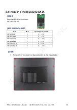
Страница 28: ...ATA SPEC Standard M 2 2242 form factor 22 x 42 x 3 2 mm M 2 2242 SATA LIST P N MLC Operating Temperature IM242S 8G M V 0 70 IM242S 16G M V 0 70 IM242S 32G M V 0 70 IM242S 64G M V 0 70 IM242S 128G M V...

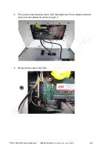
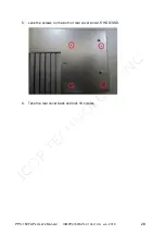
Страница 29: ...APL User s Manual IUMPPC150TAPL 01 Ver 1 0A Jun 2019 24 2 Pull up rear cover carefully which LCD Backlight and Touch cables inside the rear cover and please be careful to open it 3 Remove the screw of...

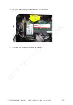
Страница 30: ...PPC 150T APL User s Manual IUMPPC150TAPL 01 Ver 1 0A Jun 2019 25 4 Plug M 2 2242 Storage on M 2 Slot and lock the screw 5 Take the rear cover back and lock 16 screws...

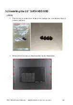
Страница 31: ...C150TAPL 01 Ver 1 0A Jun 2019 26 3 2 Installing the 2 5 SATA HDD SDD STEP 1 Find the bag of screws from inside of the package box and prepare those 4 screws in advance 2 Remove the 16 screws in a diag...

Страница 32: ...l IUMPPC150TAPL 01 Ver 1 0A Jun 2019 27 3 Pull up rear cover carefully which LCD Backlight and Touch cables inside the rear cover and please be careful to open it 4 Plug SATA cable upon 2 5 SATA HDD S...

Страница 33: ...PPC 150T APL User s Manual IUMPPC150TAPL 01 Ver 1 0A Jun 2019 28 5 Lock the screws on the both of rear cover and 2 5 HDD SSD 6 Take the rear cover back and lock 16 screws...

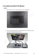
Страница 34: ...r 1 0A Jun 2019 29 3 3 Installing the Mini PCIe Module STEP 1 Remove the 16 screws in a diagonal pattern as the image below 2 Pull up rear cover carefully which LCD Backlight and Touch cables inside t...

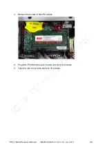
Страница 35: ...150T APL User s Manual IUMPPC150TAPL 01 Ver 1 0A Jun 2019 30 3 Remove the screw of Mini PCIe Slot 4 Plug Mini PCIe Module upon the slot and lock the screws 5 Take the rear cover back and lock 16 scre...

Страница 36: ...PPC150TAPL 01 Ver 1 0A Jun 2019 31 3 4 Installing the Micro SIM Card Must include 3G 4G Mini PCIe Module in advance STEP 1 Please refer the section 3 3 to install 3G 4G Mini PCIe Module in advance 2 P...

Страница 37: ...BIOS Instruction 4 1 Operating System Support and Drivers 4 2 BIOS Hot Key 4 3 BIOS COM1 Setting RS232 RS422 RS485 4 4 BIOS COM2 Setting Change Settings 4 5 BIOS AT Mode Setting Support Auto Power On...

Страница 38: ...10 IoT Enterprise Please get the drivers from ICOP technical support URL https www icop com tw download_resource PPC 150T N4200 tags 18 81 34 35 38 39 64 65 selected 35 For Linux most Linux distributi...

Страница 39: ...PPC 150T APL User s Manual IUMPPC150TAPL 01 Ver 1 0A Jun 2019 34 4 2 BIOS Hot Key After power on it supports BIOS hot key as below Press Del to enter the AMI BIOS setup Press F7 to enter Popup Menu...

Страница 40: ...Ver 1 0A Jun 2019 35 4 3 BIOS COM1 Setting RS232 422 485 COM1 can be set to be RS232 422 485 function Please refer the instruction as below 1 In the BIOS Setup please go to Advanced and Super IO Confi...

Страница 41: ...PPC 150T APL User s Manual IUMPPC150TAPL 01 Ver 1 0A Jun 2019 36 3 Go to Transmission Mode and set RS232 422 485 function 4 After setting please press F4 key to save exit...

Страница 42: ...ual IUMPPC150TAPL 01 Ver 1 0A Jun 2019 37 4 4 BIOS COM2 Setting Change Settings COM2 can be changed settings as below 1 In the BIOS Setup please go to Advanced and Super IO Configuration 2 Go to Seria...

Страница 43: ...T APL User s Manual IUMPPC150TAPL 01 Ver 1 0A Jun 2019 38 3 Go to Change Settings and set IO address and IRQ if you want to have the default IO 2F8h and IRQ 3 4 After setting please press F4 key to sa...

Страница 44: ...n PPC 150T APL supports Auto Power On function user doesn t need to press power button for system power on and just needs to plug power source input and system will be power on automatically 1 In the...

Страница 45: ...19 40 3 After setting please press F4 key to save exit Note After system shut down by operating system PPC 150T APL will be power off For next booting up user just needs to re plug power adapter or po...

Страница 46: ...PC150TAPL 01 Ver 1 0A Jun 2019 41 4 6 BIOS Serial Port Console Redirection PPC 150T APL supports Serial Port Console Redirection as below 1 Go to Advanced and Serial Port Console Redirection 2 Set Con...

Страница 47: ...3 Set Terminal Type to VT100 Emulation ANSI Extended ASCII char set VT100 ASCII char set VT100 Extended VT100 to support color function keys etc VT UTF8 Uses UTF8 encoding to map Unicode chars onto 1...

Страница 48: ...PPC 150T APL User s Manual IUMPPC150TAPL 01 Ver 1 0A Jun 2019 43 4 7 BIOS Load Default Setting 1 Press F3 key to load optimized defaults 2 After setting please press F4 key to save exit...

Страница 49: ...any damages lost profits lost savings or any other incidental or consequential damage resulting from the use misuse of originality to use this product Vendor will not be liable for any claim made by...

Отзывы: