15
•
Relay click duration (parameter 42) in ms
o
Minimum time during which the state of the relay does not change. This duration is guaranteed for both "active"
and "inactive" times.
o
Range = [0, 65535]
•
Detection type (parameter 72)
o
Range = [0, 1, 2]
▪
0: Inactive relay
▪
1: ITC
▪
2: Normal counting
o
Default setting = 0 (inactive)
11.2.5.3.3
Advanced relay parameter settings
The advanced relay parameter settings can be changed using the software in expert mode (ask your distributor to access the
expert mode) or by using a HyperTerminal and communicating over a RS-232 serial link.
•
Direction of detection for relay activation (parameter 063)
o
Range = [0, 1, 2]
▪
0: Receding direction
▪
1: Approaching direction
▪
2: Bi-directional
o
Default setting = 2 (bi-directional)
•
Relay state when inactive (param 67)
o
Range = [0, 1]
▪
0: non-energized relay when inactive (no detection)
▪
1: energized relay when inactive (no detection)
o
Default = 0 (non-energized when no detection)
11.2.6
Step 5
–
save the settings
Once the limits are set, send them to the radar by clicking the “Save to TMA
-
3B3” button.
11.2.7
Step 6
–
check the detections
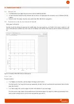
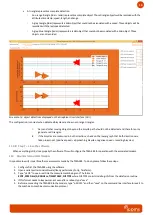
Check that the measured radar and lidar objects are properly validated (brown) of rejected (red).
•
Laser object are represented by two circles linked by a line segment. Those represent the range and duration of the
corresponding object detected by the lidar.
◦
Orange means the object has been validated by the TMA-3B3.
◦
Red means the object was rejected. It is displayed to give feedback on the current set of programmed limits.
•
Radar objects are represented by a star that represent the range, speed, and estimated time of arrival at the laser
crossing point.
◦
Orange means the object has been validated by the TMA-3B3.
◦
Red means the object was rejected. It is displayed to give feedback on the current set of programmed limits.


