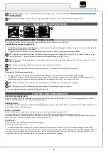
• Once the recharge cycle has been completed, disconnect the battery charger's cable from the battery connector.
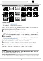
• Connect the electrical system connector (7) to the battery connector (8).
• Grip the handle (6) and turn the recovery tank to its working position.
To recharge the batteries with the on-board battery charger proceed as follows:
ATTENTION:
the following operations must be carried out by qualified personnel. An incorrect connection of the connector may cause a
malfunction of the device.
NOTE:
Carefully read the Use and Maintenance Manual of the battery charger delivered with the machine before carrying out the battery
charge cycle.
CAUTION:
before connecting the batteries to the battery charger, make sure it is suitable for the batteries used.
NOTE:
The charger power cable is delivered inside the bag containing this instruction booklet.
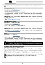
• Connect the battery charger power supply cable to the cable on the battery charger itself.
• Plug the battery charger cable into the mains socket.
•
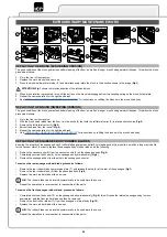
Grasp the handle (6) and turn to the charging position; the lower part of the recovery tank must be resting on the stop (10) (
Fig.11
).
CAUTION: keep the recovery tank open for the duration of the battery recharging cycle to allow gas fumes to escape.
• When the recharge cycle is complete, disconnect the battery charger power supply cable from the mains.
• Disconnect the battery charger power supply cable from the cable on the battery charger itself.
• Grip the handle (6) and turn the recovery tank to its working position.
ASSEMBLING THE BRUSH (SCRUBBING VERSION)
To assemble the brushes to bush head body, which for reasons of packaging are supplied dismantled from the machine, proceed as follows:
1. Perform the procedure for securing the machine ( see the section titled “
CAUTION:
users are advised to always wear protective gloves, to avoid the risk of serious injury to hands.
2. Raise the brush head body and fully depress the "BRUSH HEAD CONTROL" pedal (3) at the rear of the machine (
Fig.3
).
N.B.:
to lock the brush head in the raised position, depress the pedal (3) fully and then move it towards the right-hand side of the machine
(
Fig.3
).
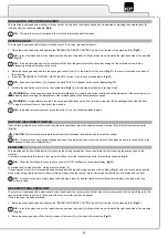
3. With the brush head in the raised position, remove the brush head splash guards (11) (
Fig.12
).
4.
Insert the brush into the flange on the brush head body, press the brush-holder plate retainer (12) and simultaneously rotate the brush in the
direction shown in the image (
Fig.13
).
ATTENTION:
Fig.13
shows the rotation direction of the left-hand brush, rotate in the opposite direction for the right-hand brush.
5. Repeat the operations completed for the right-hand front brush as well.
ASSEMBLING THE BRUSH (SWEEPING VERSION)
To assemble the brushes to bush head body, which for reasons of packaging are supplied dismantled from the machine, proceed as follows:
1. Perform the procedure for securing the machine ( see the section titled “
CAUTION:
users are advised to always wear protective gloves, to avoid the risk of serious injury to hands.
2. Raise the brush head body and detach the "BRUSH HEAD BODY CONTROL" pedal (3) at the rear of the machine from the plate retainer
(
Fig.3
).
3.
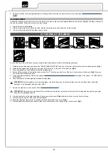
With the brush head raised from the floor, turn the knobs (13) that hold the left lateral carter (14) in place anti-clockwise (
Fig.14
).
4. Remove the left lateral carter (14) (
Fig.15
).
5. Insert the brush into the tunnel (
Fig.16
), taking care to make sure that the gearmotor drive shaft enters the slit in the brush itself.
6. Repeat the previously described operations for the right-hand side as well.
N.B.:
In order to be installed correctly, the brushes must form an X when viewed from above in the forward direction of movement (
Fig.17
).
14


