Chapter 3-Installation for 800XL
Remove the 64K DRAMS and replace them with your 256K DRAMS.
These ICs are very static sensitive so make sure you are grounded
while moving them around. Remove the old DRAMS with a small
screwdriver. Notice the notch goes to the left. Replace them with
the new 256K DRAMS making sure they also have the notch to the
left.
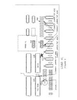
Replace U27 with RAMBO XL. Remove U27. Carefully plug RAMBO
XL into its socket with the long part of the board towards the rear.
Do not plug it in backwards. If it is plugged in correctly, you will
still be able to see the top of U26.
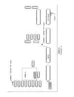
Connect all necessary jumpers. See Table 1 and Figures 3 and 4.
Use 30 gauge hookup wire for the jumper wires. Solder them from
the pads on the RAMBO XL board to the locations on the computer
as indicated in Figure 4.
Bend out the 5 pins on the PIA and connect the ribbon cable.
Remove U23, the PIA IC. Bend pins 12-16 straight out (See Figure
4). Slip the piece of shrink tubing over the ribbon cable and then
solder the ribbon cable from RAMBO XL onto the pins with the
black stripe towards the right (pin 16). Slip the shrink tubing over
the pins (to insulate them) and carefully heat the tubing just
enough to secure it from sliding back off the cable. Plug U23 back
into its socket.
Place the PCB back into the case, plug the keyboard in, and test
operation.
Reassemble your computer.
Test once again.
81
4
Содержание Ramblo XL
Страница 1: ......
Страница 2: ...An AtariPHOENIX EBook Version 1 0 Rev 1...
Страница 3: ...RAMBO XL Installation Operations Manual 256K Memory System for Atari 800XL and 1200XL Computers by ICD...
Страница 22: ...16...
Страница 24: ......
Страница 25: ......
Страница 26: ......
Страница 28: ......
Страница 29: ......
Страница 30: ......
Страница 31: ......
Страница 32: ......


