


ICC
58
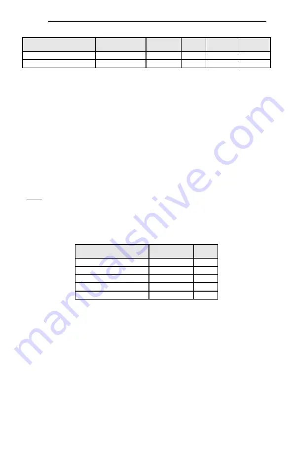
Table 26: Get/Set Attribute Single Examples
Function Code
Register Number
Service
Class
Instance
Attribute
S05 (Frequency command)
1798
0x0E / 0x10
0xA2
1798
1
M09 (Output frequency)
2058
0x0E / 0x10
0xA2
2058
1
10.2.8 Explicit Messaging Via Data Table Read/Write Services
Data table read (0x4C) and data table write (0x4D) services provide a direct method of accessing the
inverter function codes
by reference to “tag names”. Tags are read via the EtherNet/IP “data table read”
service, and written via the EtherNet/IP
“data table write” service.
To read data, the client must reference a starting “source element” and the “number of elements” to
read. Similarly, to write data, the client must reference a starting “destination element” and the “number
of elements” to write. The “number of elements” can be any quantity from 1 to the maximum allowable
length, while the “source element” and “destination element” must be tag names constructed according
to the naming conventions shown in section 10.2.9. The elements are 16-bit values.
10.2.9 Inverter Function Code Access Tag Format
Any inverter function code (refer to section 4) can be accessed with its own unique tag name, or an
array tag can be used to access a group of function codes with one PLC instruction.
The “tag name” is
essentially the ASCII representation of the function code itself. Tag names are generated according to
the following structure:
[function code group][function code offset]
Where
[function code group]
is a [1 to 2]-
character field, and is the ASCII character(s) for the function code’s
group. The characters are case-sensitive. Refer to Table 14.
[function code offset]
is a 2-character field corresponding to the function code offset. If the offset is
less than 10, it must be pre-
pended by 0. Valid offsets are “00” to “99”.
Table 27: Data Table Read/Write Examples
Function Code
Service
Tag
F07 (Acceleration time 1)
0x4C / 0x4D
F07
S05 (Frequency command)
0x4C / 0x4D
S05
M14 (Operation status)
0x4C / 0x4D
M14
W22 (Output power)
0x4C / 0x4D
W22
W168 (Life of cooling fan)
0x4C / 0x4D
W168
For explicit messaging examples, refer to sections 10.2.13 and 10.2.14.
10.2.10
ControlLogix Examples: Setup
This section will demonstrate how to initially setup a ControlLogix PLC (such as a 1756-L61) coupled
with a 1756-ENBT/A communication interface (adjust this procedure according to your specific
equipment). Later sections will provide specific read/write examples using this configuration with I/O or
explicit messaging.
1)
Run RSLogix 5000, and create a new configuration.
2)
To add a 1756-ENBT/A to your I/O configuration, first switch to offline mode.
3)
Right click on the I/O Configurat
ion node in the controller organizer view and choose “New
Module…”
4)
The “Select Module” window will open.
5)
Select the “1756-ENBT/A”, and click “Create”. Refer to Figure 27.
Содержание OPC-PRT3
Страница 20: ...ICC 19 Figure 7 Installation for 15 kW and Smaller Inverters Interface Card Connector Board Option Case...
Страница 21: ...ICC 20 Figure 8 Installation for 18 5 kW to 22 kW Inverters Interface Card Connector Board Option Case...
Страница 84: ...ICC 83 Figure 71 Monitoring the Data Being Read from the Inverter...