Chapter 4 Installation Test
Note: The adaptor is not connected to city power grid in step 1-2.
4.1 Install VTO
4.1.1 Connect wire in embedded box to VTO
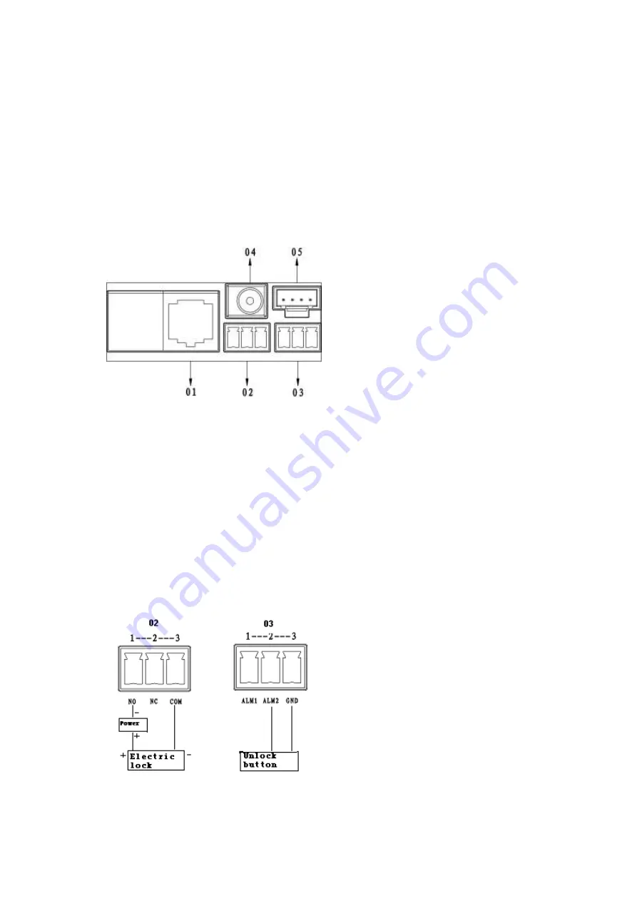
Step 1 Definition of ports:
The switch is connected to VTO’s network port.
Figure 4- 1
01. Network port: to external switch (IN port)
02. 3-pin 1: to lock control end 1
03. 3-pin 2: to lock control end 2
04. Power port: to input 12V DC power
05. Test port: to test device port
See Figure 4- 1.
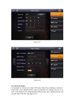
General types of lock in market are unlocking with power and unlocking without power.
Here make electric lock and Magnetic lock as example.
Step 2 Install electric lock and unlock button
Figure 4- 2
Содержание VTH
Страница 1: ...Digital Bidirectional Talk System Installation Guide V1 2 0 ...
Страница 18: ...Figure 4 23 ...


