IC Realtime ICIP-D2000VIR-B Скачать руководство пользователя страница 23


17 

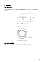
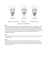
Slightly loosen the adjusting screw F and push the adjust screw F to make it swing. Adjust the lens to 

get the clear video and then fix the adjusting screw firmly.  


Step 3 

When you are securing the adjusting screw F, you can see the video may become blur. Please push the 

adjusting screw E to adjust the video slightly. Please secure the adjust screw E if you get a clear video.  


Figure 3-8 Installation 6 

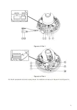
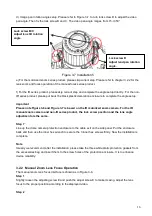
3.2.3  Side Cable Exit  

If you adopt side cable exit when you are installing the device, you need to remove the plastic decoration 

plug from the side of the chassis. Use the proper tool to dig through the part specified in Figure 3-9 to 

form a cable exit. Put the plastic decoration plug back to the chassis and then pull the cable through the 

side panel of the chassis.  


Figure 3-9 Installation 7 

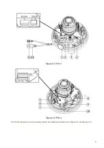
For some special user, he may need the metal protection tube to protect when he pulls through the 

cable from the side cable. There is PG11screw thread port when you pull through the cable from the 

side panel. Please remove the plastic decoration plug from the side panel of the chassis and pull 

through the cable to the tunnel of the PG11 screw thread. Now secure the tunnel in the PG11 screw 

threaded hole of the device.  


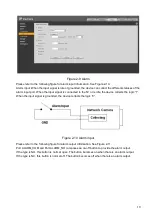
3.2.4  Cable Connection  

Dig through here 

Adjusting Screw E 


Adjusting Screw F 

Содержание ICIP-D2000VIR-B

Страница 1: ...HD IR Vandal Proof Network Dome Camera User s Manual Version 1 4 0...

Страница 2: ...r network camera This user s manual is designed to be a reference tool for your system Please read the following safeguard and warnings carefully before you use this series product Please keep this us...

Страница 3: ...cut off device during the installation connection Always follow the instruction guide the manufacturer recommended 4 Qualified engineers needed All the examination and repair work should be done by th...

Страница 4: ...ical component do not touch the enclosure when you are installing the device or clean the enclosure when you are doing maintenance work Please use professional optical clean method to clean the enclos...

Страница 5: ...directional talk 8 2 3 1 Device end to PC end 9 2 3 2 PC end to the Device end 9 2 4 Alarm Setup 9 3 Installation 12 3 1 Device Installation Introduction 12 3 2 Device Installation Steps 12 3 2 1 Gene...

Страница 6: ...v 4 1 Overview 20 4 2 Operation 20 5 Web Operation 22 5 1 Network Connection 22 5 2 Login and Main Interface 22 6 FAQ 24 Appendix Toxic or Hazardous Materials or Elements 25...

Страница 7: ...r backup function in accordance with your configuration and setup in alarm or schedule setting Support record via Web and the recorded file are storage in the client end PC Support built in Micro SD c...

Страница 8: ...Remote operation interface such as WEB DSS PSS System Status Micro SD card status bit stream statistics log and software version Video Parameter Image Sensor 1 2 8 inch CMOS Pixel 1920 H 1080 V Day N...

Страница 9: ...deo Loss Activation event alarm device audio video storage image snapshot log email function and etc Alarm Input 1 channel input 1 channel output Record and Backup Record Priority Manual External alar...

Страница 10: ...the following figures for dimension information The Unit is mm See Figure 2 1 and Figure 2 2 Figure 2 1 Dimension 1 Figure 2 2 Dimension 2 2 2 Port Description For the non IR series product the inter...

Страница 11: ...5 Figure 2 3 Port 1 Figure 2 4 Port 2 For the IR motorized zoom lens series product the interface is shown as in Figure 2 5 and Figure 2 6...

Страница 12: ...6 Figure 2 5 Port 3 Figure 2 6 Port 4 For the IR manual zoom lens series product the interface is shown as in Figure 2 7 and Figure 2 8...

Страница 13: ...the following sheet for external connection port definition information SN Port Port Name Connector Function Description 1 POWER AC 24V power port Connect to AC 24V power 2 POWER DC 12V power port Co...

Страница 14: ...efault input is DC 12V 12 LAN Network port Ethernet port The network port of the external connected cable Connect to standard Ethernet port Support PoE Please refer to the following sheet for I O port...

Страница 15: ...button becomes orange after you enabled the audio talk function Click Talk button again to stop the bidirectional talk function Please note the on site listening operation is null during the bidirect...

Страница 16: ...e device collects the logic 1 When the input signal is grounded the device collects the logic 0 Figure 2 10 Alarm input Please refer to the following figure for alarm output information See Figure 2 1...

Страница 17: ...11 Figure 2 11 Alarm output...

Страница 18: ...e installation surface can sustain at least 3X weight of the bracket and the camera 3 1 Device Installation Introduction Please refer to Figure 3 1 for device installation space information You can us...

Страница 19: ...ix firmly If you need to dig a hole to pull through the cable you need to dig a cable exit hole The diameter is more than 28mm on the installation surface according to the installation positioning map...

Страница 20: ...expansion bolts Now the chassis is secure on the installation surface Important Please earth the device GND hole GND to enhance the reliability of the device The GND port is near the cable exit of the...

Страница 21: ...ation 3 b Lens pan rotation angle setup Please refer to Figure 3 6 to unfasten the lock screw A and adjust the pan monitor angle to the proper position Then fix the lock screw A The pan angle ranges f...

Страница 22: ...d non IR series product the lock screw position and the lens angle adjustment are the same Step 7 Line up the dome camera protection enclosure to the cable exit on the side panel Put the enclosure bac...

Страница 23: ...side of the chassis Use the proper tool to dig through the part specified in Figure 3 9 to form a cable exit Put the plastic decoration plug back to the chassis and then pull the cable through the si...

Страница 24: ...pull the cable diameter ranges from 4 0 to 6 0 through the waterproof airproof plug See Figure 3 10 Figure 3 10 Cable connection Step 2 Before you go to the Step 4 in the chapter 3 2 1 installation s...

Страница 25: ...adjust the Micro SD card direction according to prompt direction Insert the card to the slot and then install the Micro SD card See Figure 3 11 Figure 3 11 Micro SD card Step 3 Please refer to Step 7...

Страница 26: ...n as in Figure 4 1 In the device list interface you can view device IP address port number subnet mask default gateway MAC address and etc Figure 4 1 Search interface Select one IP address and then ri...

Страница 27: ...o login Please note the port information here shall be identical with the port value you set in TCP port in Web Network interface Otherwise you cannot login the device If you are using device backgrou...

Страница 28: ...the PC and the network camera respectively Network camera default IP address is 192 168 1 108 Subnet mask is 255 255 255 0 Gateway is 192 168 1 1 Use order ping network camera address to check connect...

Страница 29: ...gin After you successfully logged in please install WEB plug in unit Please refer to the Web Operation Manual included in the resource CD for detailed operation instruction See Figure 5 3 Figure 5 3 W...

Страница 30: ...e via network When network upgrade operation failed you can use port 3800 to continue upgrade Recommended Micro SD card brand Kingston 4GB Kingston 1GB Kingston 16GB Transcend 16GB SanDisk 1G SanDisk...

Страница 31: ...toxic or hazardous substance or elements contained in products will not leak or mutate so that the use of these substances or elements will not result in any severe environmental pollution any bodily...

Отзывы: