MARGIN
GUIDES
Stay within the yellow
box. Do not let text go
beyond, instead move
to the next column or
start a new page.
4
|
www.icrealtime.com
2A. INSTALLATION STEPS (IPEL-F50 series)
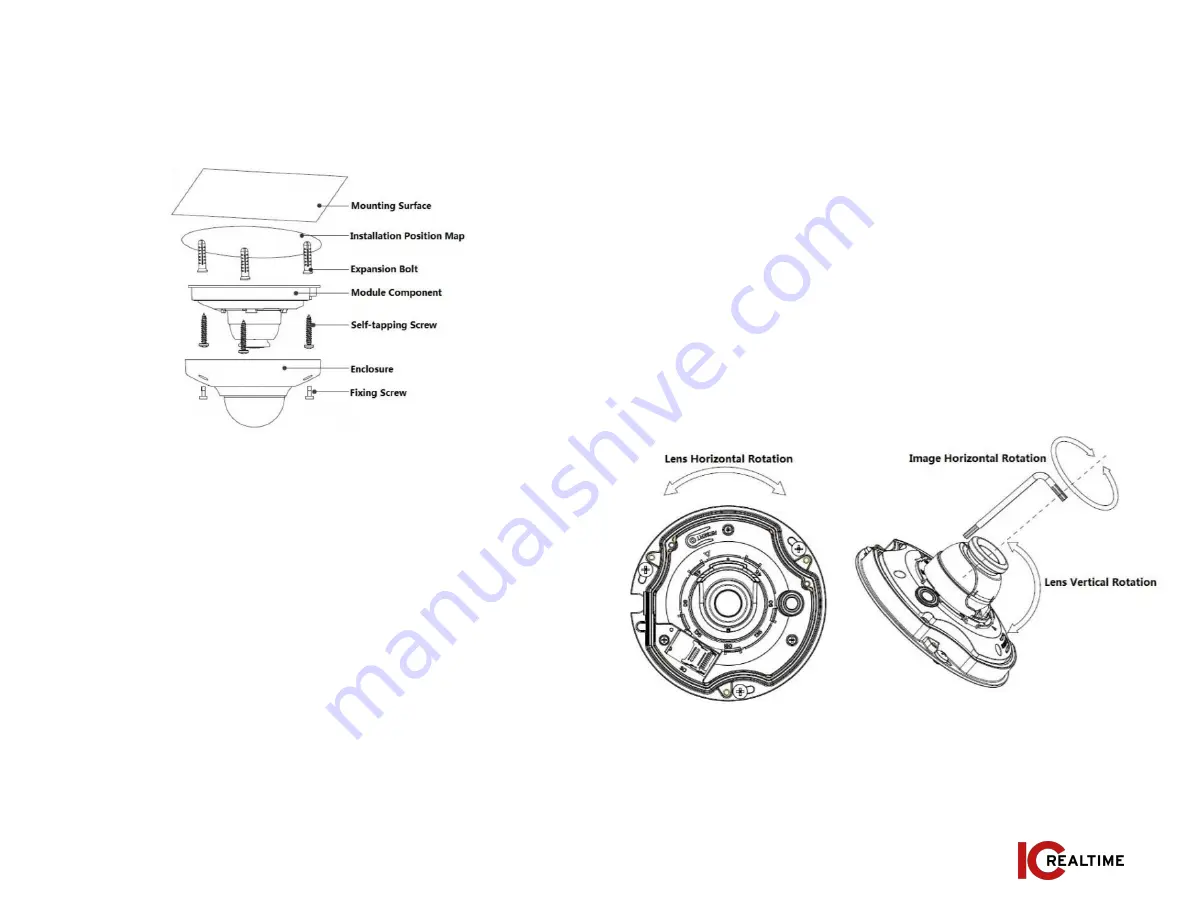
Please follow the steps listed below to install the device. Please refer
to Figure 2-3 for reference.
Figure 2-3
Step 1
Take out the installation position map and place it on the
mounting surface according to the monitoring area.
Step 2
Mark and drill bottom holes of plastic expansion bolts on the
mounting surface, insert the expansion bolts into the mounting holes.
Step 3
If necessary, drill a cable exit hole on the surface according to the
installation position map if you want to run the cable through the
installation surface when installing cable. If using the side exit, you will
need to remove the side cable exit cover on the pedestal to route the
cable through the notch.
Step 4
Align the “TOP”direction of the device with the installation
position map and then align the three screw fixing holes on the device
pedestal with the three plastic expansion bolt fixing holes on the
installation surface. Put the three self-tapping screws into the three
plastic expansion bolts and secure them firmly, and then fix the dome on
the installation surface.
Adjusting lens angle:
You can adjust the lens horizontally by hand. Use
the supplied wrench to adjust the lens vertically as well as to rotate
image rotation. See Figure 2-4.
Note:
The range of lens adjustment angle: vertical rotation direction(0°
~
+85°), image horizontal rotation direction (0°
~
+355°), image rotation
direction (0°
~
+360°).
Figure 2-4


