background image


4


Menu  

4.1


HDAVS Series DVR Settings  

Note 

The following operation and interfaces for reference only. Please refer to the HDAVS 

series 

DVR user’s manual for detailed information.  


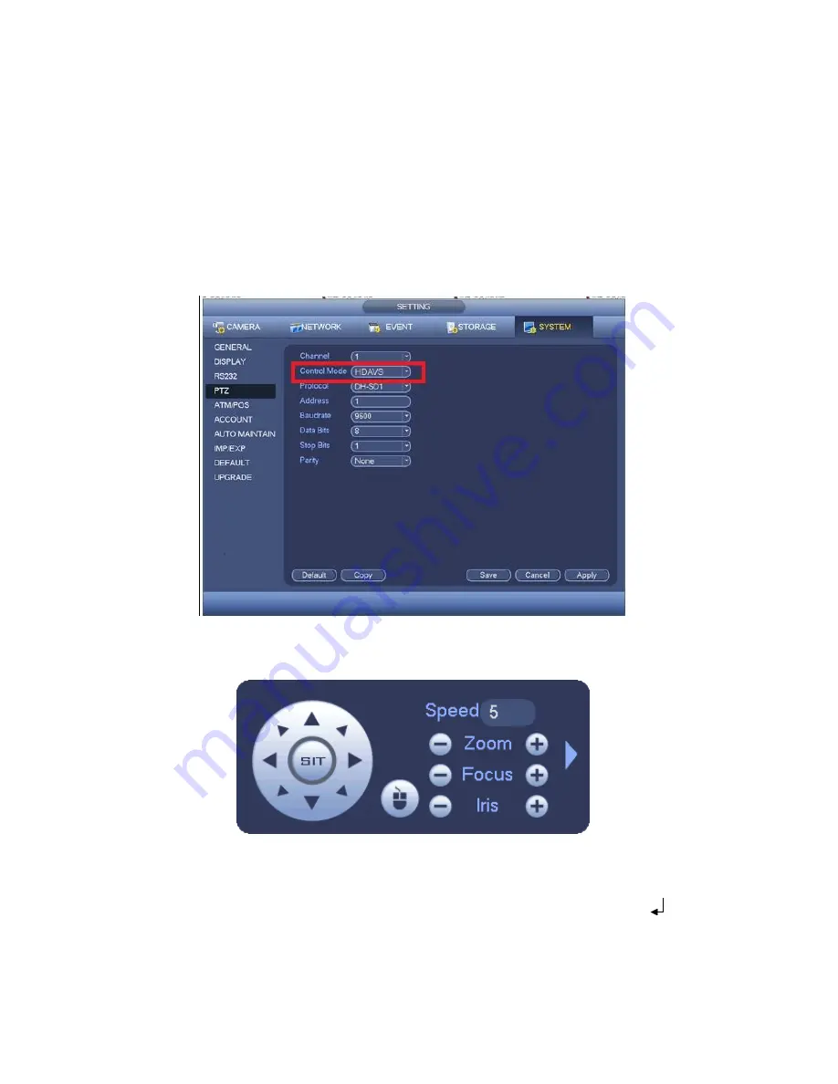
After connected the camera to the HDAVS series DVR, from Main Menu->Setting->System-

>PTZ, you need to set control mode as HDAVS and the protocol as DH-SD1. Click 

“Save” 

button to save current setup. See Figure 4-1. 


Figure 4-1 

On the preview interface, right click mouse and then select PTZ; you can see an interface 

shown as below. See Figure 4-2. 


Figure 4-2 

Click Iris 

“+” to open menu or confirm current operation.  

Click up/down button to view all the items on the left pane of the following list. Click left/right 

button to set the corresponding values on the right pane of the following list. If there is “

”, 

click confirm button to go to the 2nd menu. Repeat the previous steps to set detailed value. 

Click Return button to go back to the previous menu interface.  


Note


Содержание AVSD2208VF

Страница 1: ...HDAVS IR Vari focal Dome Camera User s Manual Version 1 0 0 ...

Страница 2: ...i Table of Contents 1 General Introduction 1 1 1 Overview 1 1 2 Features 1 1 3 Functions 1 2 Framework and Dimensions 3 3 Installation 4 4 Menu 6 4 1 HDAVS Series DVR Settings 6 ...

Страница 3: ...our HDAVS camera This user s manual is designed to be a reference tool for your system Please read the following safeguard and warnings carefully before you use this series product Please keep this user s manual well for future reference ...

Страница 4: ...tallation position can sustain the min 50N 4 Qualified engineers needed All the examination and repair work should be done by the qualified service engineers We are not liable for any problems caused by unauthorized modifications or attempted repair 5 Environment This series analog camera should be installed in a cool dry place away from direct sunlight or strong light inflammable explosive substa...

Страница 5: ...ork Use the dry soft cloth to clean the device If there is too much dust please use the water to dilute the mild detergent first and then use it to clean the device Finally use the dry cloth to clean the device Please put the dustproof cap to protect the CMOS component when you do not use the camera ...

Страница 6: ...v Applicable model This manual can be applied to the following model AVS D2208 VF ...

Страница 7: ...ies support 720P 25 720P 30 720P 50 720P 60 Low end series only support 720P 25 720P 30 1080P series support 1080P 25 1080P 30 720P 25 720P 30 720P 50 720P 60 Low end series only support 1080P 25 1080P 30 Support high performance 3D noise reduction denoise Not supported by low end series excellent performance in low illumination Support ICR switch to realize surveillance both in the daytime and at...

Страница 8: ...ht compensation according to the environment illumination 3D NR Comparing with the general 2D denoise function the 3D denoise function can not only denoise the brightness of the video separation signal and saturation signal it can also denoise the original data from CCD It greatly enhances noise reduction performance and guarantees clear and bright video ...

Страница 9: ... 2 2 Figure 2 1 Figure 2 2 When the standard definition high definition switch control cable is short circuit system outputs standard definition video Otherwise when the circuit is open system outputs the high definition video Low end series supports HD output but doesn t support SD output which also has no HD SD switch control cable ...

Страница 10: ...m accessories bag and put them into the installation holes and fix them Step 2 Open decoration ring and take down enclosure and dome body Step 3 Adjust the pedestal position according to the cable exit mode ceiling side Pull the cable through the cable side exit at the installation surface and the pedestal Please skip this step if you want to use ceiling exit mode Line up the screw holes at the bo...

Страница 11: ...angle for monitoring according to the direction which is shown in Figure 3 1 Step 5 Connect the video output port of the device cable to the back end encoding device and connect the power port of the device to power supply Step 6 After the image is displayed on the back end encoding device adjust the focusing nut which is inside of zoom adjustment hole and focus adjustment hole by focusing tool to...

Страница 12: ... setup See Figure 4 1 Figure 4 1 On the preview interface right click mouse and then select PTZ you can see an interface shown as below See Figure 4 2 Figure 4 2 Click Iris to open menu or confirm current operation Click up down button to view all the items on the left pane of the following list Click left right button to set the corresponding values on the right pane of the following list If ther...

Страница 13: ...re are subject to change without prior written notice All trademarks and registered trademarks mentioned are the properties of their respective owners If there is any uncertainty or controversy please refer to the final explanation of us Please visit our website or contact your local service engineer for more information ...

Отзывы: