


preliminary
preliminary
iC-PZ AN1
GETTING STARTED GUIDE iC-PZ
Rev A1, Page 5/10
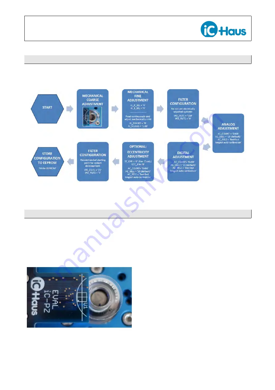
ADJUSTMENT PROCEDURE OVERVIEW
Figure 5: Order of adjustment procedures
PROCEDURE FOR MECHANICAL ADJUSTMENT
Best measurement results are achieved at the ideal
mechanical position. iC-PZ supports this process of
finding the ideal position by offering white marks on the
scanner module for coarse adjustment and dynamic
values in the GUI for fine adjustment.
Mechanical coarse adjustment
Figure 6: White
marks
on
scanner
module
(iC-PZ2656 EVAL PZ1M) for mechanical
coarse adjustment
•
White marks on top of the scanner module
(iC-PZ2656 EVAL PZ1M) help to easily find the coarse
position of the sensor iC with respect to the code track.
The scanner module is moved until the curved white
mark completes the cicumference of the code disc as
shown in Figure 6. Note that the recommended air
gap betweeen code disc and sensor is 1 mm to 2 mm.
Mechanical fine adjustment
•
Rotate/ move at least at minimum speed required for
the automatic analog adjustment. The following val-
ues are recommended:
Rotary (iC-PZ2656): 300 RPM
Linear (iC-PZ205): 25.6 cm/s
•
In the GUI tab ’Signal Conditioning’ section ’Digital Ad-
justment’ enable dynamic phase and dynamic scale
adjustment by setting
AI_S_SEL = ’4’ [ = 0x04]
AI_P_SEL = ’4’ [ = 0x04]
•
Continuously read AI_PHASES and AI_SCALES. The
registers show the currently effective adjustment val-
ues and are marked with a yellow frame in Figure


