


238
IBM eX5 Implementation Guide
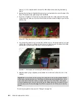
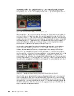
The cable end must slide into the port until it clicks into place. You can disengage the
retainer that holds the cable in place by pressing on the blue tab on the top of the QPI
cable connection.
QPI cables for connecting QPI ports 1 to 1 and 4 to 4 must be installed, regardless of
whether processors 2 and 3 are installed, to allow the secondary node to be controlled by
the primary node. If one of the cables is detached, the server cannot power on.
QPI cables must be installed for each of the processors installed. Table 6-5 describes the
QPI port on the back of the server with the corresponding processor socket in the server.
Table 6-5 QPI port relationship to the processor socket
After you attach the cables, connect the power to both nodes of the complex.
When the power status light changes from a rapidly blinking light to a slow blinking green
light, press the power button on the primary node. Both nodes power up. If both nodes do not
power up, double check that the required matching firmware is on both nodes of the server.
You must disconnect the QPI cables to determine if the required matching firmware is on both
nodes of the server.
If neither node powers up or the secondary node does not power up, consider swapping QPI
cables between port 1 on both nodes to one of the cross-port cables between ports 2 and 3. If
this action proves unsuccessful, do the same task with the QPI cables between port 4 of both
nodes and again one of the two crossed QPI cables between ports 2 and 3. There are
additional communication lanes on port 1 for synchronization of the CPU frequencies and
additional communication lines on port 4 for communication between the FPGA of the
primary node and the secondary node. If this approach works, check the IMM event log for
any QPI link failures between processors to see if one of the cross-linked QPI cables between
ports 2 and 3 needs to be replaced. Frequently, one of the critical QPI cables was not
completely seated.
After the complex is up and running, double check the IMM event log for any QPI link failures.
The error message reports which processors experience the error. Based on Table 6-5, the
processor reporting the QPI link error points to a QPI cable on a specific port. Provided the
two nodes are running matched IMM and FPGA, the problem can be the processor or QPI
port on either end of the QPI cable or the cable itself. The cable is the most likely point of
failure.
After the two nodes boot as a single entity, any firmware flashes applied to the primary node
are automatically applied to the secondary node.
6.6 PCIe adapters and riser card options
This section describes considerations to remember for determining how to use your PCIe
slots, depending on the types of PCIe riser cards that you have installed. The x3850 X5 is an
enterprise server that is designed to function in a high availability cluster or powerful
QPI port number
Processor socket number
1
4
2
3
3
2
4
1
Содержание x3850 X5
Страница 2: ......
Страница 3: ...International Technical Support Organization IBM eX5 Implementation Guide May 2011 SG24 7909 00...
Страница 20: ...xviii IBM eX5 Implementation Guide...
Страница 32: ...12 IBM eX5 Implementation Guide...
Страница 34: ...14 IBM eX5 Implementation Guide...
Страница 74: ...54 IBM eX5 Implementation Guide...
Страница 136: ...116 IBM eX5 Implementation Guide...
Страница 238: ...218 IBM eX5 Implementation Guide...
Страница 392: ...372 IBM eX5 Implementation Guide...
Страница 466: ...446 IBM eX5 Implementation Guide...
Страница 484: ...464 IBM eX5 Implementation Guide Figure 9 14 IMM Remote Control Video Viewer showing power control options...
Страница 560: ...540 IBM eX5 Implementation Guide...
Страница 564: ...544 IBM eX5 Implementation Guide...
Страница 578: ...IBM eX5 Implementation Guide IBM eX5 Implementation Guide...
Страница 579: ......


